1OPERATION_.pdf - 第201页
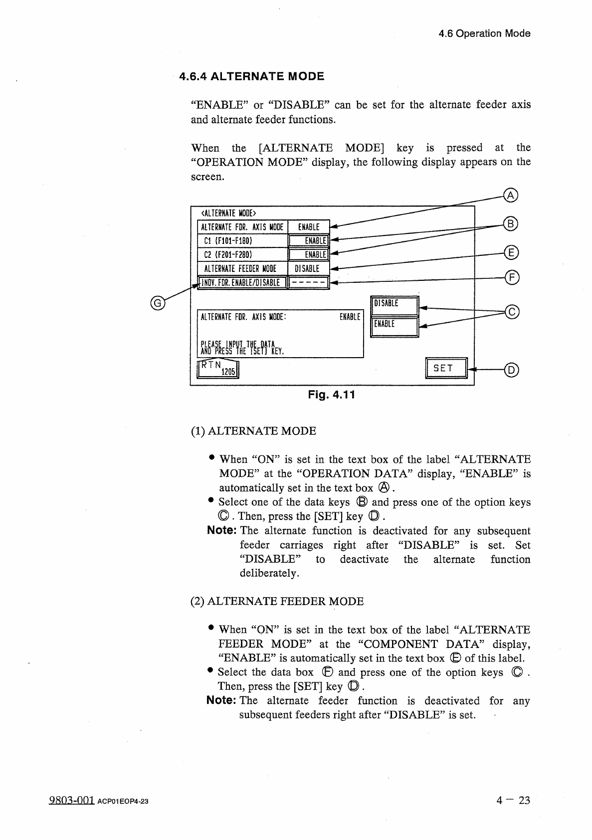
4.6 Operation Mode 4.6 . 4 ALTERNATE MODE “ ENABLE ” or “ DISABLE ” can be set for the alternate feeder axis and alternate feeder functions . When the [ ALTERNATE MODE ] key is pressed at the “ OPERATION MODE ” display ,…
4.6
Operation
Mode
Notes
:
(
a
)
When
“
DISABLE
”
is
set
in
the
data
box
of
the
label
“
DETECTION
MODE
”
,
this
function
is
not
activated
and
does
not
detect
any
component
shortage
at
every
lane
.
Any
component
shortage
error
message
does
not
appear
in
the
text
box
of
the
label
“
MGT
.
INFO
.
’’
.
(
b
)
When
“
ENABLE
”
is
set
,
it
becomes
possible
not
to
detect
specific
feeder
(
lane
)
.
any
component
shortage
Especially
when
the
tape
end
cannot
be
detected
on
a
correctly
,
set
“
DISABLE
”
in
the
text
box
for
such
taped
components
.
Use
the
component
library
data
to
specify
“
DISABLE
”
for
the
specific
feeder
(
lane
)
.
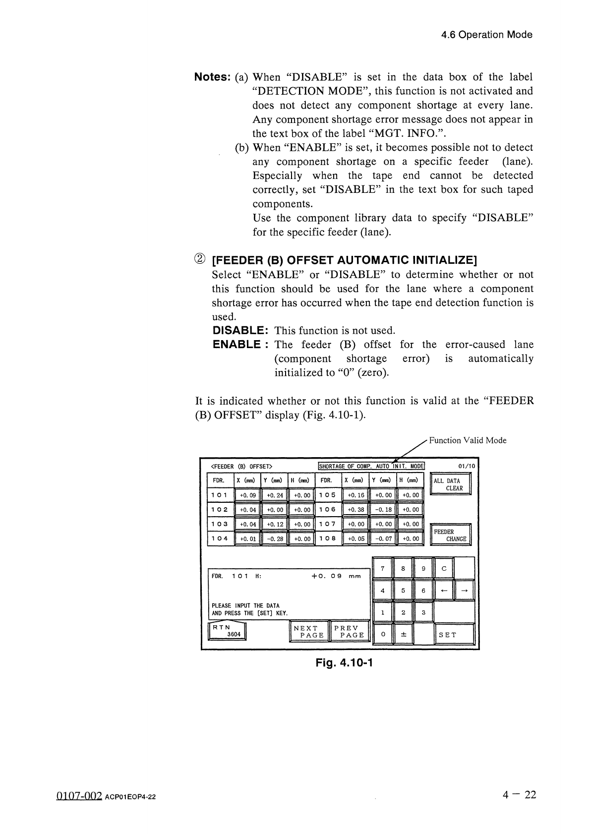
②
[
FEEDER
(
B
)
OFFSET
AUTOMATIC
INITIALIZE
]
Select
“
ENABLE
”
or
“
DISABLE
”
to
determine
whether
or
not
this
function
should
be
used
for
the
lane
where
a
component
shortage
error
has
occurred
when
the
tape
end
detection
function
is
used
.
DISABLE
:
This
function
is
not
used
.
ENABLE
:
The
feeder
(
B
)
offset
for
the
error
-
caused
lane
(
component
shortage
error
)
is
automatically
initialized
to
“
0
”
(
zero
)
.
It
is
indicated
whether
or
not
this
function
is
valid
at
the
“
FEEDER
(
B
)
OFFSET
”
display
(
Fig
.
4.10
-
1
)
.
Function
Valid
Mode
INIL
MODEI
ISHORTAGE
OF
COMP
.
AUTO
"
〈
FEEDER
(
B
)
OFFSET
〉
01
/
10
X
(
mm
)
Y
(
mm
)
H
(
mm
)
X
(
mm
)
Y
(
mm
)
H
(
mm
)
FDR
.
FDR
.
ALL
DATA
CLEAR
+
0.09
+
0.16
+
0
.
00
+
0
.
00
+
0
.
24
+
0.00
1 0
6
+
0.38
-
0.18
+
0
.
00
+
0.04
+
0.00
+
0.00
10
7
1
03
+
0.04
+
0
.
12
+
0.00
+
0.00
+
0.00
+
0
.
00
FEEDER
+
0
.
05
-
0.07
+
0.00
CHANGE
+
0.01
-
0.28
+
0.00
7
8
C
FDR
.
10
1
H
:
+
0.0
9
PLEASE
INPUT
THE
DATA
AND
PRESS
THE
[
SET
]
KEY
.
3
f
*
RT
N
^
^
TI
3604
H
PREV
PAGE
NEXT
PAGE
0
±
SET
Fig
.
4.10
-
1
4
-
22
0107
-
002
ACP
01
EOP
4
-
22
4.6
Operation
Mode
4.6
.
4
ALTERNATE
MODE
“
ENABLE
”
or
“
DISABLE
”
can
be
set
for
the
alternate
feeder
axis
and
alternate
feeder
functions
.
When
the
[
ALTERNATE
MODE
]
key
is
pressed
at
the
“
OPERATION
MODE
”
display
,
the
following
display
appears
on
the
screen
.
《
ALTERNATE
MODE
)
B
ALTERNATE
FDR
.
AXIS
MODE
ENABLE
ENABLE
]
Cl
(
F
101
-
F
180
)
E
INMEI
C
2
(
F
201
-
F
280
)
ALTERNATE
FEEDER
MODE
DISABLE
-
©
iNOV
.
FDR
.
ENABLE
/
DISABLE
DISABLE
ENABLE
ALTERNATE
FDR
.
AXIS
MODE
:
ENABLE
齜
WHE
?
fV
<
2
)
SET
Fig
.
4.11
(
1
)
ALTERNATE
MODE
•
When
“
ON
”
is
set
in
the
text
box
of
the
label
“
ALTERNATE
MODE
”
at
the
“
OPERATION
DATA
”
display
,
‘
automatically
set
in
the
text
box
@
.
#
Select
one
of
the
data
keys
©
and
press
one
of
the
option
keys
◎
.
Then
,
press
the
[
SET
]
key
◎
.
Note
:
The
alternate
function
is
deactivated
for
any
subsequent
‘
ENABLE
,,
is
feeder
carriages
right
after
“
DISABLE
”
is
set
.
Set
“
DISABLE
:
to
deactivate
the
alternate
function
deliberately
.
(
2
)
ALTERNATE
FEEDER
MODE
•
When
“
QN
”
is
set
in
the
text
box
of
the
label
“
ALTERNATE
FEEDER
MODE
”
at
the
“
COMPONENT
DATA
”
display
,
“
ENABLE
”
is
automatically
set
in
the
text
box
©
of
this
label
.
•
Select
the
data
box
®
and
press
one
of
the
option
keys
©
.
Then
,
press
the
[
SET
]
key
©
.
Note
:
The
alternate
feeder
function
is
deactivated
for
any
subsequent
feeders
right
after
“
DISABLE
”
is
set
.
980
^
-
001
4
-
2 3
ACP
01
EOP
4
-
23
4.6
Operation
Mode
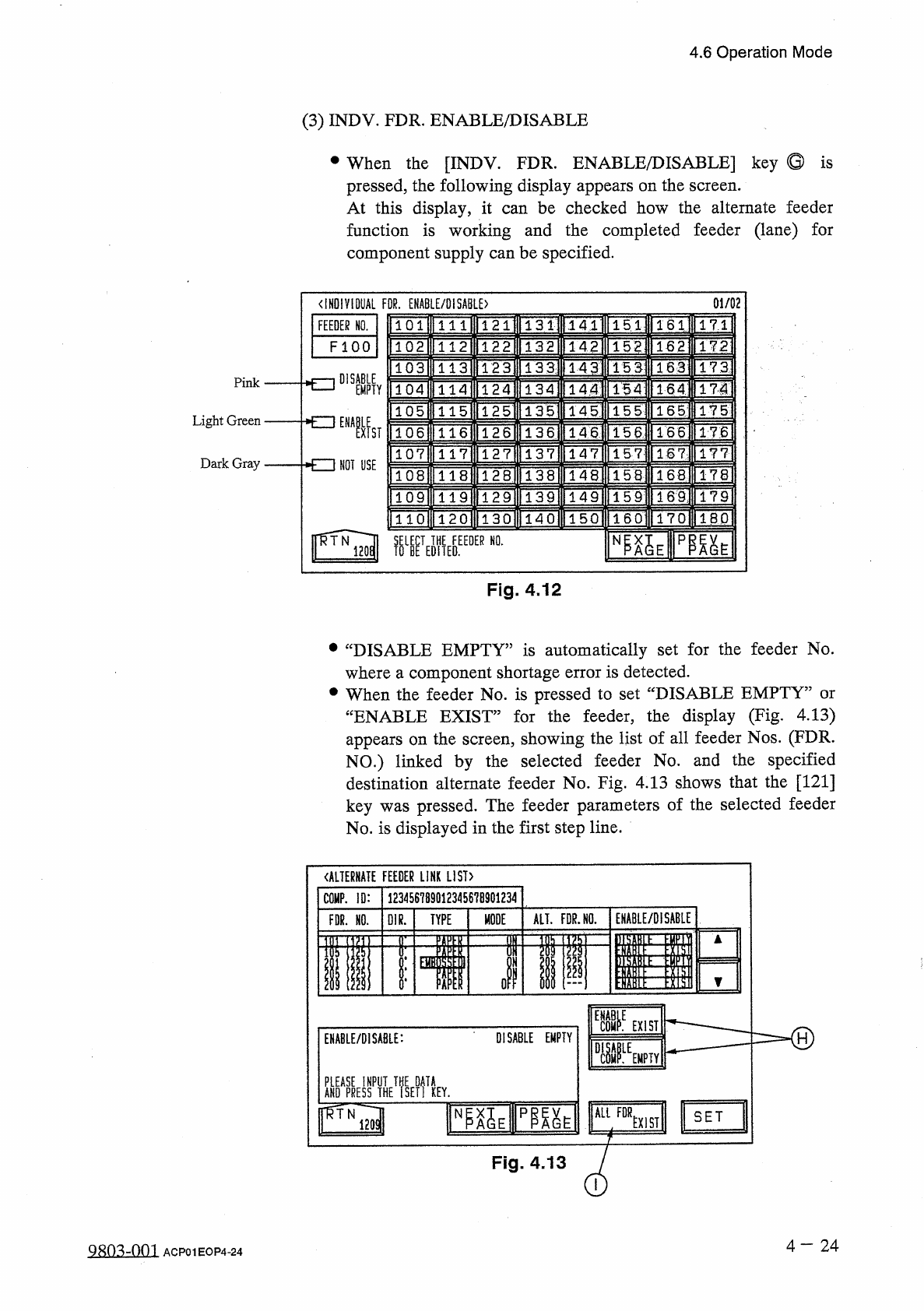
(
3
)
INDV
.
FDR
.
ENABLE
/
DISABLE
•
When
the
[
INDV
.
FDR
.
ENABLE
/
DISABLE
]
key
Q
is
pressed
,
the
following
display
appears
on
the
screen
.
At
this
display
,
it
function
is
working
and
the
completed
feeder
(
lane
)
for
component
supply
can
be
specified
.
can
be
checked
how
the
alternate
feeder
01
/
02
<
IHD
!
V
10
UAL
FOR
.
ENABLE
/
DISABLE
)
131
|
FEEDER
NO
.
151
171
141
1611
111
F l O O
132
142
152
162
172
1 12
133
]
HU
173
15
3
113
143
DISABLE
Pink
TSAI
TlH
171
144
154
EMPTY
114
1351
145
IFg
]
15
5
115
Light
Green
NOT
USE
136
llT
4
l
"
1661
TT
6
15
6
116
ns
147
117
157
177
Dark
Gray
1681
178
118
156
lWi
ITM
1
TFs
]
IT
?
159
119
T
4
~
0
lT
50
l
ITTol
1
~
6
CI
1701
IBP
1 2 0
NI
^
E
pm
^
Fig
.
4.12
•
“
DISABLE
EMPTY
”
is
automatically
set
for
the
feeder
No
.
where
a
component
shortage
error
is
detected
.
•
When
the
feeder
No
.
is
pressed
to
set
“
DISABLE
EMPTY
”
or
“
ENABLE
EXIST
”
for
the
feeder
,
the
display
(
Fig
.
4.13
)
appears
on
the
screen
,
showing
the
list
of
all
feeder
Nos
.
(
FDR
.
NO
.
)
linked
by
the
selected
feeder
No
.
and
the
specified
destination
alternate
feeder
No
.
Fig
.
4.13
shows
that
the
[
121
]
key
was
pressed
.
The
feeder
parameters
of
the
selected
feeder
No
.
is
displayed
in
the
first
step
line
.
《
ALTERNATE
FEEDER
LINK
LIST
)
123456789
Q
12345678901234
COMP
.
ID
:
ENABLE
/
DISABLE
ALT
.
FDR
.
HO
.
MODE
FDR
.
HO
.
01
R
.
TYPE
«
II
ill
ol
ii
i
]
E
11111
=
=
=
=
=
=
-
®
EXIST
DISABLE
EMPTY
ENABLE
/
DISABLE
:
fSE
?
f
!
KEY
.
ALL
FOR
NP
^
E
pm
^
SET
EXIST
Fig
.
4.13
4
-
24
QRO
^
-
Om
ACP
01
EOP
4
-
24