1OPERATION_.pdf - 第218页
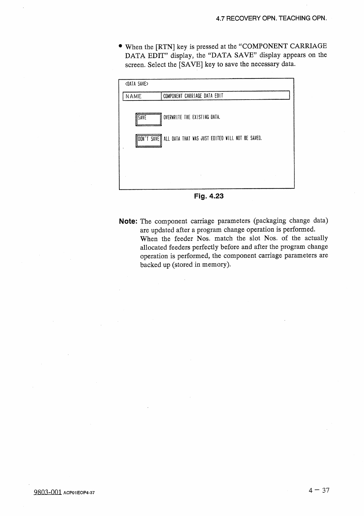
4.7 RECOVERY OPN . TEACHING OPN . at the “ COMPONENT CARRIAGE • When the [ RTN ] key is pressed DATA EDIT ” display , the “ DATA SAVE ” display appears on the screen . Select the [ SAVE ] key to save the necessary data .…
llSCREENS
C
lTHKNS
.
t
]
|
VEOr
|
)
THKHiCHKn
COMPONENT
ID
FDR
.
〈
COMPONENT
CARRIAGE
DATA
EDIT
>
4.7
RECOVERY
OPN
.
TEACHING
OPN
.
•
When
“
BULK
2
”
is
set
in
the
“
TYPE
”
text
field
,
“
”
appears
in
the
“
DIR
”
text
field
,
indicating
that
the
direction
cannot
be
changed
.
•
When
“
BULK
2
”
is
set
in
the
“
TYPE
”
text
field
,
the
tape
end
detection
function
cannot
be
activated
.
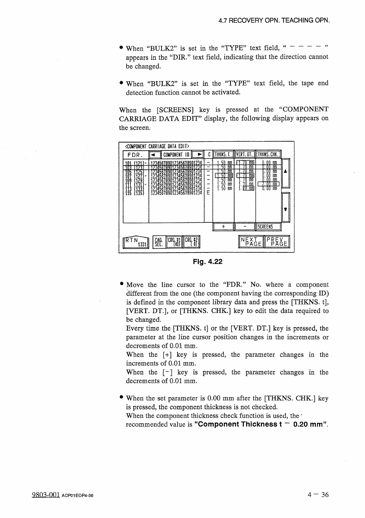
When
the
[
SCREENS
]
key
is
pressed
at
the
“
COMPONENT
CARRIAGE
DATA
EDIT
”
display
,
the
following
display
appears
on
the
screen
.
Fig
.
4.22
•
Move
the
line
cursor
to
the
“
FDR
.
”
No
.
where
a
component
different
from
the
one
(
the
component
having
the
corresponding
ID
)
is
defined
in
the
component
library
data
and
press
the
[
THKNS
.
t
]
,
[
VERT
.
DT
.
]
,
or
[
THKNS
.
CHK
.
]
key
to
edit
the
data
required
to
be
changed
.
Every
time
the
[
THKNS
.
t
]
or
the
[
VERT
.
DT
.
]
key
is
pressed
,
the
parameter
at
the
line
cursor
position
changes
in
the
increments
or
decrements
of
0.01
mm
.
When
the
[
+
]
key
is
pressed
,
the
parameter
changes
in
the
increments
of
0.01
mm
.
When
the
[
-
]
key
is
pressed
,
the
parameter
changes
in
the
decrements
of
0.01
mm
.
•
When
the
set
parameter
is
0.00
mm
after
the
[
THKNS
.
CHK
.
]
key
is
pressed
,
the
component
thickness
is
not
checked
.
When
the
component
thickness
check
function
is
used
,
the
*
recommended
value
is
“
Component
Thickness
t
一
0.20
mm
”
.
9
sn
^
-
nm
4
-
36
ACP
01
EOP
4
-
36
u
議刪關凰凰
|
1
]
11
)
Mss
刪
nlni
瞧
腿聊
4
/
u
444
30
J
333
Qiolol
i
I
4
L
414
iJT
*
4
i
ooooo
889
SS
RW
666
r
3
rD
5
rD
44444
330
JOJ
3
ot
2
n
/
5
L
2
15710911122
4.7
RECOVERY
OPN
.
TEACHING
OPN
.
at
the
“
COMPONENT
CARRIAGE
•
When
the
[
RTN
]
key
is
pressed
DATA
EDIT
”
display
,
the
“
DATA
SAVE
”
display
appears
on
the
screen
.
Select
the
[
SAVE
]
key
to
save
the
necessary
data
.
〈
DATA
SAVE
〉
COMPONENT
CARRIAGE
DATA
EDIT
NAME
OVERWRITE
THE
EXISTING
DATA
.
D
0
N
*
T
SAVE
ALL
OATA
THAT
VAS
JUST
EDITED
VILL
HOT
BE
SAVED
.
Fig
.
4.23
Note
:
The
component
carriage
parameters
(
packaging
change
data
)
are
updated
after
a
program
change
operation
is
performed
.
When
the
feeder
Nos
.
match
the
slot
Nos
.
of
the
actually
allocated
feeders
perfectly
before
and
after
the
program
change
operation
is
performed
,
the
component
carriage
parameters
are
backed
up
(
stored
in
memory
)
.
4
一
37
980
^
-
001
ACP
01
EOP
4
-
37
4.7
RECOVERY
OPN
.
TEACHING
OPN
.
Concrete
Example
of
Simplified
Packaging
Direction
Change
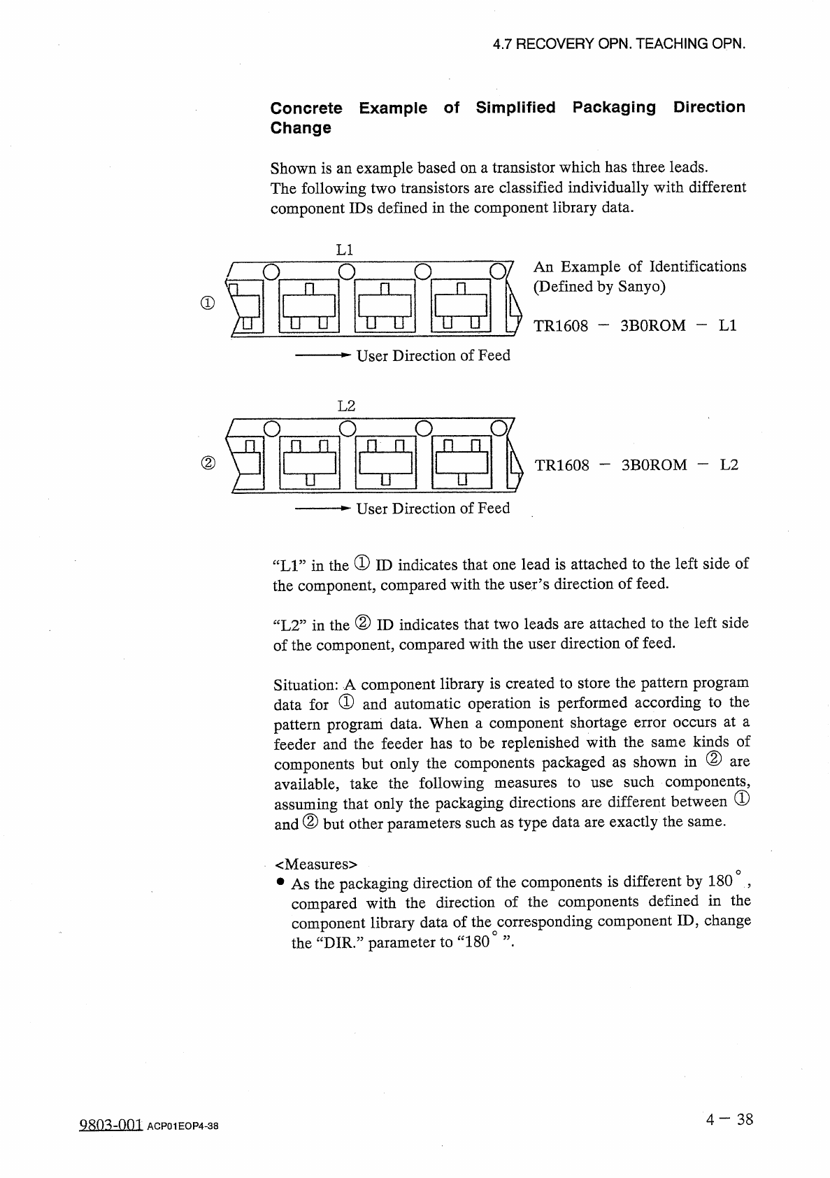
Shown
is
an
example
based
on
a
transistor
which
has
three
leads
.
The
following
two
transistors
are
classified
individually
with
different
component
IDs
defined
in
the
component
library
data
.
LI
0
/
An
Example
of
Identifications
(
Defined
by
Sanyo
)
n
o
n
n
R
①
TTU
ITU
nu
TR
1608
-
3
BOROM
-
LI
User
Direction
of
Feed
L
2
O
/
o
a
o
n
门
门
n
n
n
②
3
BOROM
—
L
2
TR
1608
u
n
u
User
Direction
of
Feed
“
LI
”
in
the
①
ID
indicates
that
one
lead
is
attached
to
the
left
side
of
the
component
,
compared
with
the
user
’
s
direction
of
feed
.
“
L
2
”
in
the
②
ID
indicates
that
two
leads
are
attached
to
the
left
side
of
the
component
,
compared
with
the
user
direction
of
feed
.
Situation
:
A
component
library
is
created
to
store
the
pattern
program
data
for
①
and
automatic
operation
is
performed
according
to
the
pattern
program
data
.
When
a
component
shortage
error
occurs
at
a
feeder
and
the
feeder
has
to
be
replenished
with
the
same
kinds
of
components
but
only
the
components
packaged
as
shown
in
②
available
,
take
the
following
assuming
that
only
the
packaging
directions
are
different
between
(
D
and
②
but
other
parameters
such
as
type
data
are
exactly
the
are
such
components
,
measures
to
use
same
.
<
Measures
>
•
As
the
packaging
direction
of
the
components
is
different
by
180
,
compared
with
the
direction
of
the
components
defined
in
the
component
library
data
of
the
corresponding
component
ID
,
change
the
“
DIR
.
”
parameter
to
“
180
°
”
•
4
-
38
Q
^
Q
^
-
001
ACP
01
EOP
4
-
38