1OPERATION_.pdf - 第221页
4.8 Product Change Operation 4.8 Product Change Operation When the [ PRODUCT CHANGE ] key is pressed at the “ AUTO OPN . SUB - MENU ” display , the following display appears on the screen . Note : When the [ PRODUCT CHAN…
4.7
RECOVERY
OPN
.
TEACHING
OPN
.
4.7
.
4
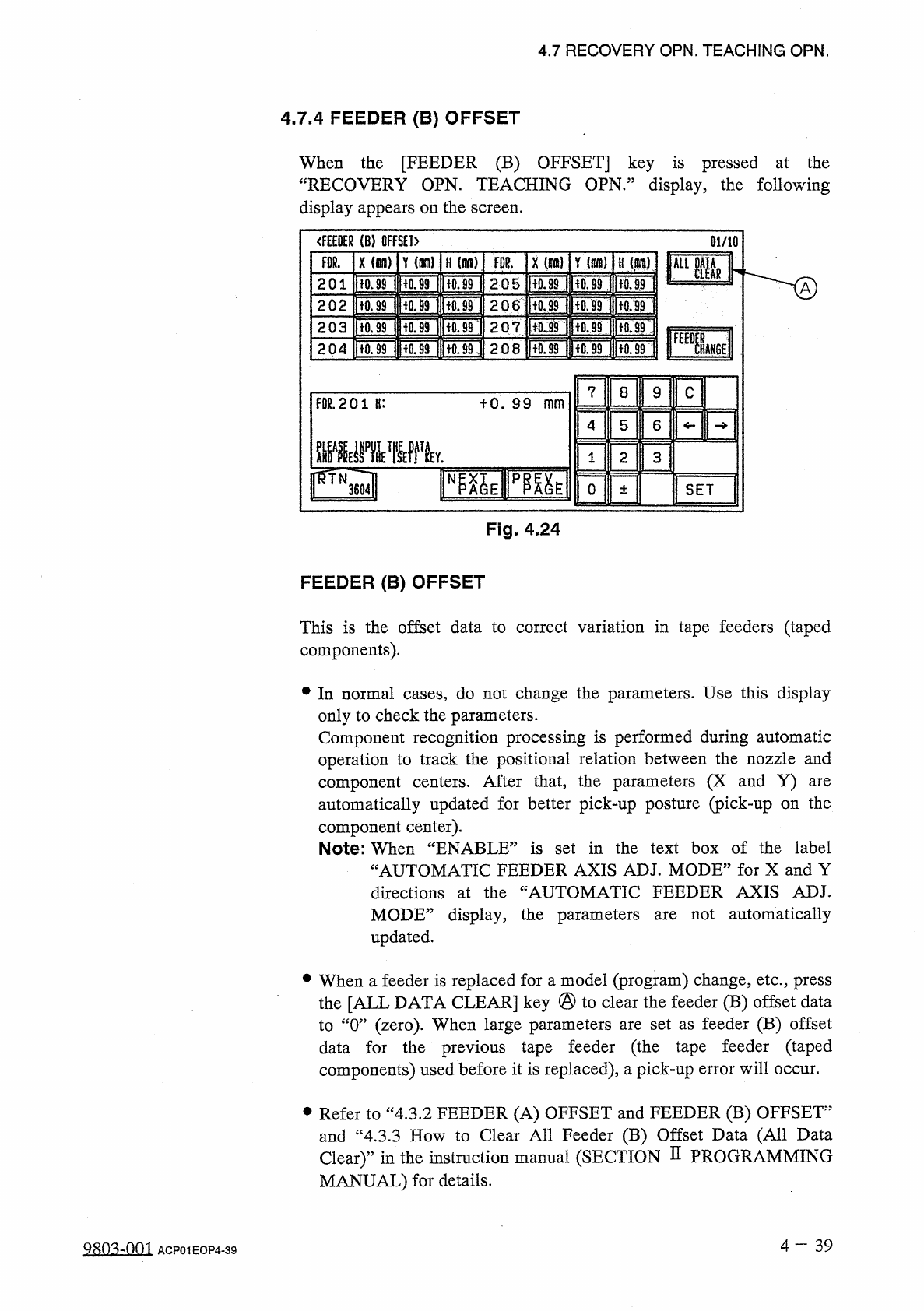
FEEDER
(
B
)
OFFSET
When
the
[
FEEDER
(
B
)
OFFSET
]
key
is
pressed
at
the
“
RECOVERY
OPN
.
TEACHING
OPN
.
”
display
,
the
following
display
appears
on
the
screen
.
<
FE
£
BER
(
B
)
OFFSET
)
01
/
10
軍
Y
(
ran
)
FDR
.
X
(
Hi
)
Y
{
mm
)
H
)
X
(
wn
)
H
(
it
)
ALIMR
[
Ton
iron
non
Ron
pfon
IfO
.
M
201
2.05
2
o
6
iron
lion
隨
ncsTi
non
Hon
[
rorinorji
'
iori
202
203
207
:
IfOriROjlfTOd
lioniiiriiTof
204
208
7
8
9
c
FOR
.
201
H
:
十
0
.
99
mm
4
5
6
2
1
3
FQl
NP
^
E
pmt
o
SET
±
Fig
.
4.24
FEEDER
(
B
)
OFFSET
This
is
the
offset
data
to
correct
variation
in
tape
feeders
(
taped
components
)
.
•
In
normal
cases
,
do
not
change
the
parameters
.
Use
this
display
only
to
check
the
parameters
.
Component
recognition
processing
is
performed
during
automatic
operation
to
track
the
positional
relation
between
the
nozzle
and
component
centers
.
After
that
,
the
parameters
(
X
and
Y
)
automatically
updated
for
better
pick
-
up
posture
(
pick
-
up
on
the
component
center
)
.
Note
:
When
“
ENABLE
”
is
set
in
the
text
box
of
the
label
“
AUTOMATIC
FEEDER
AXIS
ADJ
.
MODE
”
for
X
and
Y
directions
at
the
“
AUTOMATIC
FEEDER
AXIS
ADJ
.
MODE
”
display
,
the
parameters
updated
.
are
not
automatically
are
•
When
a
feeder
is
replaced
for
a
model
(
program
)
change
,
etc
.
,
press
the
[
ALL
DATA
CLEAR
]
key
@
to
clear
the
feeder
(
B
)
offset
data
to
“
0
”
(
zero
)
.
When
large
parameters
are
set
as
feeder
(
B
)
offset
data
for
the
previous
tape
feeder
(
the
tape
feeder
(
taped
components
)
used
before
it
is
replaced
)
,
a
pick
-
up
error
will
occur
.
•
Refer
to
“
4.3
.
2
FEEDER
(
A
)
OFFSET
and
FEEDER
(
B
)
OFFSET
”
and
“
4.3
.
3
How
to
Clear
All
Feeder
(
B
)
Offset
Data
(
All
Data
Clear
)
”
in
the
instruction
manual
(
SECTION
H
PROGRAMMING
MANUAL
)
for
details
.
4
—
3 9
9803
-
001
ACP
01
EOP
4
-
39
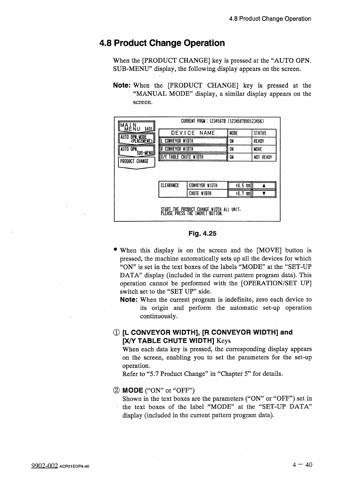
4.8
Product
Change
Operation
4.8
Product
Change
Operation
When
the
[
PRODUCT
CHANGE
]
key
is
pressed
at
the
“
AUTO
OPN
.
SUB
-
MENU
”
display
,
the
following
display
appears
on
the
screen
.
Note
:
When
the
[
PRODUCT
CHANGE
]
key
is
pressed
at
the
“
MANUAL
MODE
”
display
,
a
similar
display
appears
on
the
screen
.
CURRENT
PR
6
M
:
12345678
(
1234567890123456
)
STATUS
DEVICE
NAME
MODE
AUTO
OPN
.
M
L
CONVEYOR
V
1
DTH
<
PLAC
fEAOY
OH
R
CONVEYOR
麵
PRODUCT
CHANGE
QN
HOVE
X
/
Y
TABLE
CHUTE
jflQTH
m
NOT
READY
fO
.
5
晒
CLEARANCE
CONVEYOR
V
10
TH
iO
.
7
m
\
CHUTE
WIDTH
醚
kmifi
鼴
M
醞
A
“
UNIT
-
Fig
.
4.25
and
the
[
MOVE
]
button
is
pressed
,
the
machine
automatically
sets
up
all
the
devices
for
which
“
ON
”
is
set
in
the
text
boxes
of
the
labels
“
MODE
”
at
the
“
SET
-
UP
DATA
”
display
(
included
in
the
current
pattern
program
data
)
.
This
operation
cannot
be
performed
with
the
[
OPERATION
/
SET
UP
]
switch
set
to
the
“
SET
UP
”
side
.
Note
:
When
the
current
program
is
indefinite
,
zero
each
device
to
its
origin
and
perform
the
automatic
set
-
up
operation
continuously
.
•
When
this
display
is
on
the
screen
①
[
L
CONVEYOR
WIDTH
]
,
[
R
CONVEYOR
WIDTH
]
and
[
X
/
Y
TABLE
CHUTE
WIDTH
]
Keys
When
each
data
key
is
pressed
,
the
corresponding
display
appears
on
the
screen
,
enabling
you
to
set
the
parameters
for
the
set
-
up
operation
.
Refer
to
“
5.7
Product
Change
”
in
“
Chapter
5
”
for
details
.
②
MODE
(
“
ON
:
Shown
in
the
text
boxes
are
the
parameters
(
“
ON
”
or
ccOFF
?
?
)
set
in
the
text
boxes
of
the
label
“
MODE
”
at
the
“
SET
-
UP
DATA
”
display
(
included
in
the
current
pattern
program
data
)
.
OFF
”
)
or
4
—
4 0
9902
-
002
ACP
01
EOP
4
-
40
4.8
Product
Change
Operation
③
STATUS
“
MOVE
,,
“
READY
5
:
The
machine
is
performing
the
set
-
up
operation
.
The
set
-
up
operation
is
completed
and
the
width
is
set
as
“
P
.
C
.
B
.
Width
+
Clearance
”
•
fNOT
READY
”
:
The
width
is
set
as
“
P
.
C
.
B
.
Width
+
Clearance
”
but
the
current
position
is
not
located
(
managed
)
.
”
:
The
current
position
or
program
is
indefinite
.
f
”
(
Red
)
:
“
OFF
”
is
set
as
set
-
up
data
.
④
CLEARANCE
“
CLEARANCE
”
is
the
data
which
gives
some
leeway
to
the
actual
conveyor
and
chute
widths
,
adding
some
value
to
the
parameter
Y
set
as
P
.
C
.
B
.
size
in
the
current
pattern
program
data
.
(
This
is
not
related
to
the
P
.
C
.
B
.
support
pins
up
/
down
movement
.
)
(
No
parameter
can
be
set
for
each
individual
pattern
program
data
.
)
•
The
data
input
range
is
The
actual
conveyor
and
X
/
Y
table
chute
widths
must
be
“
P
.
C
.
B
.
Size
Y
+
Clearance
(
Recommended
Value
0.5
mm
)
”
.
一
5.0
十
5.0
mm
”
.
Input
Method
of
Clearance
Data
•
After
selecting
the
key
of
the
data
to
be
set
,
press
the
[
A
]
key
to
the
value
or
[
▼
]
key
to
decrease
in
the
increments
or
increase
decrements
of
0.1
mm
.
•
When
the
value
is
out
of
the
input
range
,
the
buzzer
in
the
touch
screen
sounds
but
no
change
is
made
in
the
parameter
.
of
the
devices
is
being
Note
:
No
data
can
be
changed
while
activated
.
one
4
-
41
ACP
01
EOP
4
-
41