1OPERATION_.pdf - 第267页
4.11 Setting of Automatic Offset Teaching Mode ⑨ ( A ) ADJUSTMENT The set parameter is used to calculate the head offset ( master ) based on the positional deviation when the deviation of the component recognition camera…
4.11
Setting
of
Automatic
Offset
Teaching
Mode
(
Second
Page
)
This
is
protected
by
the
password
in
the
same
level
as
that
of
the
teaching
session
(
various
head
/
nozzle
offset
data
)
.
⑤
[
EDIT
DATA
]
Key
When
this
key
is
selected
,
the
“
HEAD
.
NOZZLE
OFFSET
TEACH
-
EDIT
DATA
-
”
display
appears
on
the
screen
.
⑥
[
SELECT
MODE
]
Key
When
this
key
is
selected
,
the
-
SELECT
MODE
-
”
display
appears
on
the
screen
.
fHEAD
.
NOZZLE
OFFSET
TEACH
(
Third
Page
)
This
is
protected
by
the
password
in
the
same
level
as
that
of
the
offset
data
editing
session
.
⑧
PLACE
.
POS
.
ADJ
.
MODE
•
This
function
is
used
to
adjust
the
component
placement
position
which
has
deviated
from
the
correct
one
due
to
the
changes
in
the
environmental
condition
(
temperature
,
etc
.
)
.
•
When
“
ENABLE
”
is
set
in
this
data
box
,
the
head
offset
(
master
)
data
(
used
to
adjust
the
deviation
of
the
component
placement
position
)
is
calculated
by
the
following
formula
after
the
completion
of
the
automatic
teaching
operation
(
including
the
manual
teaching
operation
)
.
•
As
the
head
offset
(
master
)
data
is
calculated
according
to
the
variations
in
the
head
center
offset
and
the
head
center
(
B
)
offset
,
it
is
required
to
set
the
head
center
(
B
)
offset
before
the
automatic
teaching
function
is
implemented
.
•
Open
the
“
HEAJ
>
NOZZLE
OFFSET
TEACH
”
display
.
(
Hierarchical
Sequence
:
“
SPECIAL
SEL
”
Display
—
“
OFFSET
TEACH
”
Display
一
^
HEAD
-
NOZZLE
OFFSET
TEACH
”
Display
)
When
the
[
TEACH
DATA
COPY
OPN
.
]
key
is
pressed
at
this
display
,
the
head
center
offset
is
copied
to
the
head
center
(
B
)
offset
.
(
Refer
to
“
3.5
.
1
Head
*
Nozzle
Offset
Teaching
”
in
“
SECTION
1
MAINTENANCE
MANUAL
”
for
details
.
)
4
-
85
9902
-
003
ACP
01
EOP
4
-
85
4.11
Setting
of
Automatic
Offset
Teaching
Mode
⑨
(
A
)
ADJUSTMENT
The
set
parameter
is
used
to
calculate
the
head
offset
(
master
)
based
on
the
positional
deviation
when
the
deviation
of
the
component
recognition
camera
position
is
regarded
as
“
1
”
.
(
Default
:
2.33
)
⑩
(
B
)
ADJUSTMENT
The
set
parameter
represents
the
rate
of
the
actual
placement
position
adjustment
and
is
used
to
calculate
the
head
offset
(
master
)
.
(
Default
:
100
%
)
4
—
85
-
1
QQ
02
-
002
ACP
01
EOP
4
-
85
-
1
4.11
Setting
of
Automatic
Offset
Teaching
Mode
(
1
)
Editing
of
Specified
Parameters
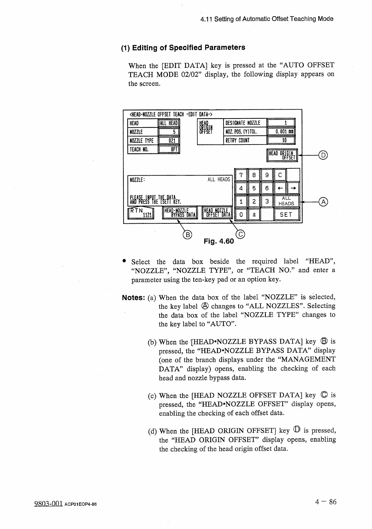
When
the
[
EDIT
DATA
]
key
is
pressed
at
the
“
AUTO
OFFSET
TEACH
MODE
02
/
02
”
display
,
the
following
display
appears
on
the
screen
.
<
HEA
0
*
N
0
ZZLE
OFFSET
TEACH
-
EDIT
DATA
-
)
ALL
HEADI
DESIGNATE
NOZZLE
HEAD
Ilf
N
0
Z
.
P
0
S
.
(
YITOL
.
0.001
HH
1
NOZZLE
5
RETRY
COUNT
10
NOZZLE
TYPE
021
ID
TEACH
HO
.
<
§
)
HEAD
IN
SET
8
C
7
9
ALL
HEADS
NOZZLE
:
5
6
4
腿
yiwk
ALL
o
2
3
1
HEADS
o
SET
±
®
Fig
.
4.60
®
•
Select
the
data
box
beside
the
required
label
“
HEAD
”
,
“
NOZZLE
,
,
,
“
NOZZLE
TYPE
,
,
,
parameter
using
the
ten
-
key
pad
or
an
option
key
.
TEACH
NO
.
”
and
enter
a
or
Notes
:
(
a
)
When
the
data
box
of
the
label
“
NOZZLE
”
is
selected
,
the
key
label
@
changes
to
“
ALL
NOZZLES
”
.
Selecting
the
data
box
of
the
label
“
NOZZLE
TYPE
”
changes
to
the
key
label
to
“
AUTO
”
.
(
b
)
When
the
[
HEAD
-
NOZZLE
BYPASS
DATA
]
key
©
is
display
the
“
HEAD
-
NOZZLE
BYPASS
DATA
5
pressed
,
(
one
of
the
branch
displays
under
the
“
MANAGEMENT
DATA
”
display
)
opens
,
enabling
the
checking
of
each
head
and
nozzle
bypass
data
.
(
c
)
When
the
[
HEAD
NOZZLE
OFFSET
DATA
]
key
©
is
pressed
,
the
“
HEAJ
>
NOZZLE
OFFSET
”
display
opens
,
enabling
the
checking
of
each
offset
data
.
(
d
)
When
the
[
HEAD
ORIGIN
OFFSET
]
key
◎
is
pressed
,
the
“
HEAD
ORIGIN
OFFSET
”
display
opens
,
enabling
the
checking
of
the
head
origin
offset
data
.
4
—
8 6
Q
80
^
-
nm
ACP
01
EOP
4
-
86