1OPERATION_.pdf - 第271页
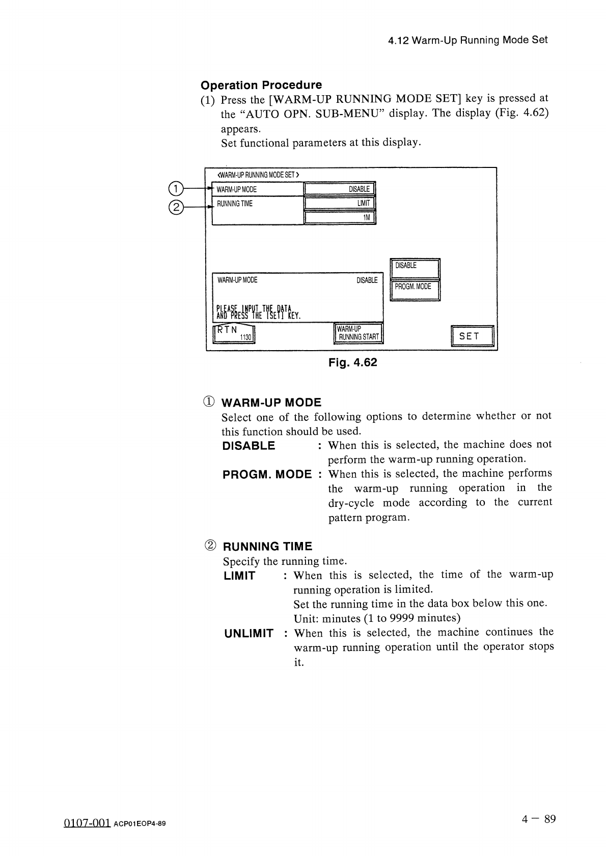
4.12 Warm - Up Running Mode Set Operation Procedure ( 1 ) Press the [ WARM - UP RUNNING MODE SET ] key is pressed at the “ AUTO OPN . SUB - MENU ” display . The display ( Fig . 4.62 ) appears . Set functional parameters …
4.12
Warm
-
Up
Running
Mode
Set
4.12
Warm
-
Up
Running
Mode
Set
Simplifying
the
warm
-
up
running
operation
reduces
the
changes
in
temperature
(
deterioration
with
age
)
around
the
DD
head
and
the
rotary
turret
,
stabilizing
and
improving
the
accuracy
of
component
placement
.
Note
:
The
automatic
teaching
function
belongs
to
this
function
as
a
supporting
one
.
Restrictions
of
Warm
-
Up
Running
Mode
(
1
)
This
function
works
in
the
“
TEST
”
mode
regardless
of
the
test
mode
settings
at
the
“
TEST
MODE
”
display
.
(
2
)
The
SIF
function
does
not
work
.
(
3
)
The
trash
box
fill
-
up
warning
function
does
not
work
.
(
4
)
The
maintenance
warning
function
does
not
work
.
(
5
)
The
automatic
teaching
function
does
not
work
.
(
6
)
The
same
restrictions
as
those
in
the
normal
running
mode
applies
to
the
ET
communication
.
(
7
)
The
warm
-
up
running
time
is
added
as
“
TEST
MODE
TIME
”
at
the
“
MANAGEMENT
DATA
”
display
.
Starting
the
Warm
-
Up
Running
Operation
(
1
)
Activate
the
machine
in
the
dry
-
cycle
mode
according
to
the
current
pattern
program
.
The
machine
does
not
perform
any
component
picks
,
component
placement
operation
,
P
.
C
.
B
.
transfer
operation
,
etc
.
,
at
all
.
As
the
machine
performs
a
transfer
operation
in
the
dry
-
cycle
mode
,
it
is
required
to
remove
the
P
.
C
.
B
.
’
s
from
the
transfer
section
and
the
X
/
Y
table
.
It
is
recommended
that
an
exclusive
pattern
program
for
the
warm
-
up
running
operation
be
prepared
for
better
efficiency
.
(
2
)
The
“
OPN
.
MODE
”
display
stays
active
during
the
running
operation
.
For
safety
purposes
,
any
operations
at
a
display
during
the
warm
-
up
running
operation
.
Once
the
machine
is
set
in
the
“
STOP
”
mode
,
another
display
can
be
opened
.
warm
-
up
prohibited
are
(
3
)
This
function
works
for
the
period
of
time
specified
in
the
menu
.
4
-
88
0107
-
001
ACP
01
EOP
4
-
88
4.12
Warm
-
Up
Running
Mode
Set
Operation
Procedure
(
1
)
Press
the
[
WARM
-
UP
RUNNING
MODE
SET
]
key
is
pressed
at
the
“
AUTO
OPN
.
SUB
-
MENU
”
display
.
The
display
(
Fig
.
4.62
)
appears
.
Set
functional
parameters
at
this
display
.
<
WARM
-
UPRUNNING
MODESET
>
WARM
-
UP
MODE
DISABLE
RUNNING
TIME
LIMIT
1
M
DISABLE
WARM
-
UP
MODE
DISABLE
PROGM
.
MODE
PLEASE
IHPUTTHE
DATA
nfrN
WARM
-
UP
RUNNING
START
SET
1130
Fig
.
4.62
①
WARM
-
UP
MODE
Select
one
of
the
following
options
to
determine
whether
or
not
this
function
should
be
used
.
DISABLE
:
When
this
is
selected
,
the
machine
does
not
perform
the
warm
-
up
running
operation
.
PROGM
.
MODE
:
When
this
is
selected
,
the
machine
performs
the
warm
-
up
running
operation
in
the
dry
-
cycle
mode
according
to
the
current
pattern
program
.
②
RUNNING
TIME
Specify
the
running
time
.
LIMIT
:
When
this
is
selected
,
the
time
of
the
warm
-
up
running
operation
is
limited
.
Set
the
running
time
in
the
data
box
below
this
one
.
Unit
:
minutes
(
1
to
9999
minutes
)
:
When
this
is
selected
,
the
machine
continues
the
warm
-
up
running
operation
until
the
operator
stops
UNLIMIT
it
.
4
-
89
0107
-
001
ACP
01
EOP
4
-
89

4.12
Warm
-
Up
Running
Mode
Set
Notes
:
Items
to
be
checked
before
operation
start
(
a
)
Warm
-
Up
Running
Operation
The
machine
does
not
perform
any
warm
-
up
running
operation
in
the
“
PLACE
”
or
the
“
PASS
”
mode
.
Confirm
that
“
PLACE
”
is
set
for
the
current
pattern
program
and
“
PLACE
.
MODE
”
is
indicated
above
the
[
PASS
/
PLACE
.
CHANGE
]
key
at
the
“
AUTO
OPN
.
SUB
-
MENU
”
display
.
The
vacuum
pump
is
automatically
turned
“
OFF
”
during
the
warm
-
up
running
operation
.
Be
sure
not
to
perform
the
warm
-
up
running
operation
with
a
component
being
picked
up
.
(
b
)
Remove
the
P
.
C
.
B
.
’
s
from
the
conveyor
and
the
X
/
Y
table
if
there
are
P
.
C
.
B
.
’
s
on
them
.
When
there
is
a
P
.
C
.
B
.
(
s
)
on
the
conveyor
and
/
or
the
X
/
Y
table
,
a
warning
message
is
issued
on
the
screen
.
(
c
)
When
another
message
is
issued
at
a
“
CHECK
”
display
,
check
the
contents
and
remove
the
cause
of
the
startup
error
.
•
After
specifying
each
parameter
,
press
the
[
WARM
-
UP
RUNNING
START
]
key
.
The
“
WARM
-
UP
RUNNING
〈
PLACEMENT
〉
,
,
display
(
Fig
.
4.63
)
appears
.
07
/
23
/
2001
(
MON
)
17
:
56
:
30
V
Z
3
2
1
6
C
6
I
STOP
I
I
WARM
-
UP
RUNNING
〈
PLACEMENT
〉
CURRENT
PRGM
:
COMMENT
«
1
U O O
-
P O O O O
(
O
)
F
O O
O
N O
.
:
F O O O
<
S
E
P
A
R A
T
E
D
>
S T E P
N O
.
F D R
.
氺 氺 氺氺 氺
ORIGIN
MONITOR
氺 氺 氺氷 氺
«
P
.
C
.
B
.
COUNTER
»
ROTARY
TURRET
RECOGNITION
P
.
C
.
B
.
TRANSFER
X
/
Y
TABLE
CAMERA
X
/
Y
FEEDER
AXIS
COMP
.
PICK
-
UP
(
Z
)
L
CNVR
.
WD
.
COMP
.
PLACE
.
(
Z
)
R
CNVR
.
WD
.
INPUT
MACHINE
OUTPUT
MACHINE
FURNACE
X
/
Y
CHUTE
WD
.
PROS
.
PROD
.
6
7
2
0
1
《
P
.
C
.
B
.
PRCS
.
TIME
))
10.05
SEC
.
HEAD
RUNNING
TIME
SET
:
1
M
Fig
.
4.63
0107
-
001
4
-
90
ACP
01
EOP
4
-
90