1OPERATION_.pdf - 第287页
5.6 Manual Axis Operation ( distance ) ( angle ) , the corresponding display shows the scale to be used . ( index angle ) , the corresponding display does • When data is entered using the unit ce cc mm or When the unit i…
5.6
Manual
Axis
Operation
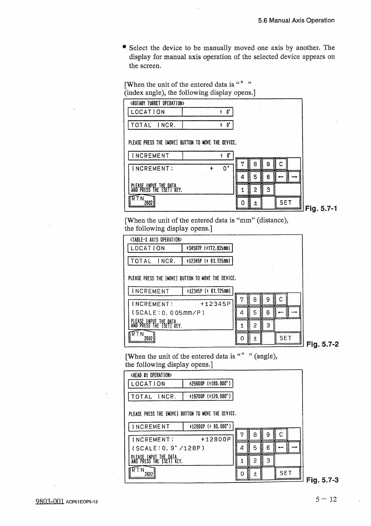
•
Select
the
device
to
be
manually
moved
one
axis
by
another
.
The
display
for
manual
axis
operation
of
the
selected
device
appears
on
the
screen
.
[
When
the
unit
of
the
entered
data
is
“
0
’
’
(
index
angle
)
,
the
following
display
opens
.
]
〈
ROTARY
TURRET
OPERATION
〉
LOCATION
+
0
.
TOTAL
iNCR
.
t
0
#
PLEASE
PRESS
THE
[
MOVE
]
BUTTON
TO
MOVE
THE
DEVICE
.
t
0
*
INCREMENT
9
C
7
8
INCREMENT
:
0
*
5
6
4
3
2
1
fRTN
2602
SET
0
土
Fig
.
5.7
-
1
[
When
the
unit
of
the
entered
data
is
“
mm
”
(
distance
)
,
the
following
display
opens
.
]
<
IABLE
-
X
AXIS
OPERATION
)
LOCATION
十
34567
P
(
t
!
72.835
mm
)
TOTAL
l
NCR
.
+
12345
F
(
t
61725
mD
)
PLEASE
PRESS
THE
IMOVE
]
BUTTON
TO
MOVE
THE
DEVICE
.
INCREMENT
H
2345
P
(
t
61.725
刪
I
C
7
8
9
INCREMENT
:
(
SCALE
:
0
.
0
05
mm
/
P
)
罪霍
十
12345
P
5
6
4
3
2
1
Y
.
pTN
2602
SET
O
土
Fig
.
5.7
-
2
[
When
the
unit
of
the
entered
data
is
“
°
”
(
angle
)
,
the
following
display
opens
.
]
<
HEAD
li
OPERATION
)
音
25600
P
(
t
!
80.000
,
)
LOCATION
+
19200
P
(
H
20.000
*
)
TOTAL
I
NCR
.
PLEASE
PRESS
THE
[
MOVE
]
BUTTON
TO
HOVE
THE
DEVICE
.
f
!
2800
P
(
t
90
.
000
*
)
1
NCREMENT
C
7
8
9
十
12800
P
INCREMENT
:
(
SCALE
:
0
.
9
m
/
128
P
)
5
6
4
TA
2
3
KEY
.
1
rvi
SET
O
土
Fig
.
5.7
-
3
5
一
12
QRO
^
-
nm
ACP
01
EOP
5
-
12
5.6
Manual
Axis
Operation
(
distance
)
(
angle
)
,
the
corresponding
display
shows
the
scale
to
be
used
.
(
index
angle
)
,
the
corresponding
display
does
•
When
data
is
entered
using
the
unit
ce
cc
mm
or
When
the
unit
is
“
not
show
any
scale
.
Displayed
Scale
Data
Input
Range
Device
Name
土
360
(
。
)
土
99999
(
p
)
土
99999
(
p
)
土
99999
(
p
)
土
99999
(
p
)
土
99999
(
p
)
土
99999
(
p
)
土
99999
(
^
)
None
0.005
mm
/
P
0.005
mm
/
P
1
mm
/
300
P
0.005
mm
/
P
0.005
mm
/
P
1
mm
/
300
P
0.9
°
/
128
P
Rotary
Turret
X
Table
Y
Table
Component
Pick
-
Up
(
Z
)
Axis
Camera
X
Camera
Y
Placement
Z
Axis
Head
#
s
1
16
•
Enter
data
in
the
text
box
of
the
label
“
INCREMENT
”
and
press
the
[
SET
]
key
according
to
the
resolution
of
each
device
.
The
selected
device
moves
according
to
the
set
amount
and
stops
.
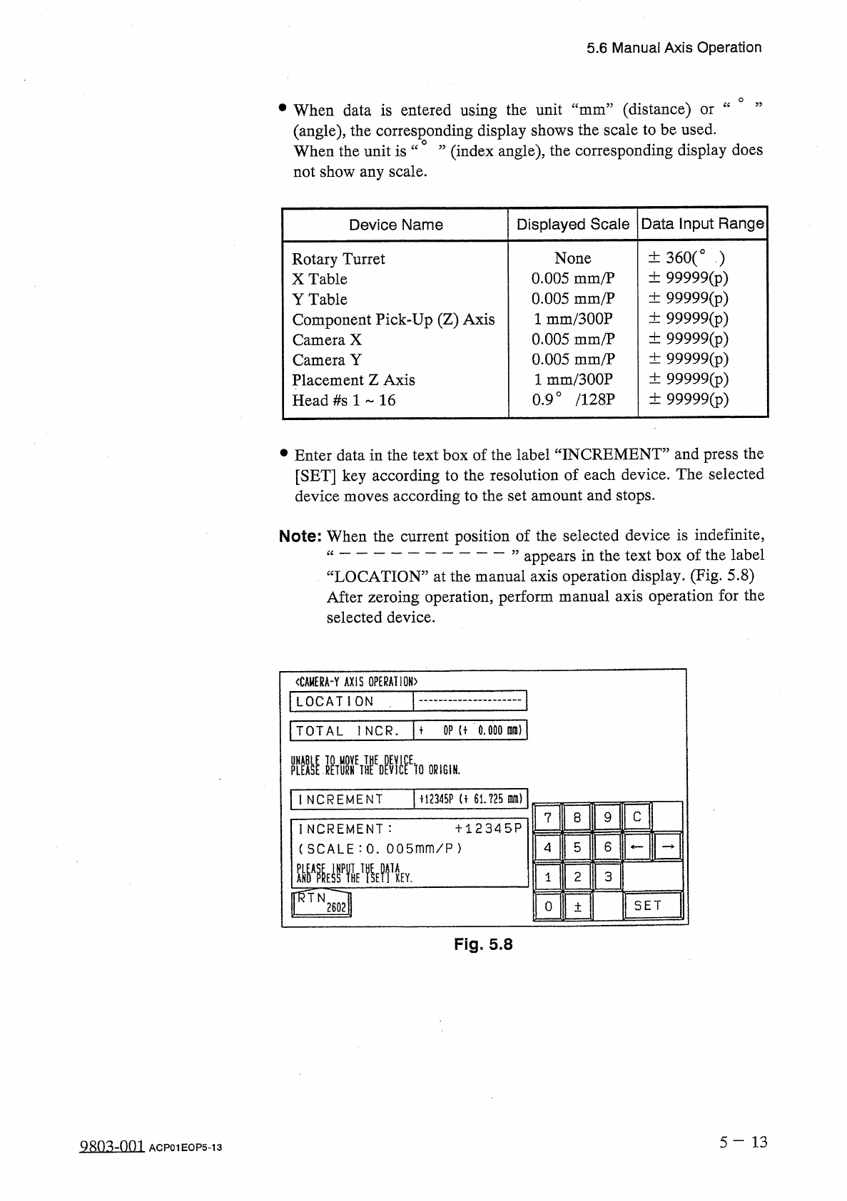
Note
:
When
the
current
position
of
the
selected
device
is
indefinite
,
“
”
appears
in
the
text
box
of
the
label
“
LOCATION
”
at
the
manual
axis
operation
display
.
(
Fig
.
5.8
)
After
zeroing
operation
,
perform
manual
axis
operation
for
the
selected
device
.
<
CAMERA
-
Y
AXIS
OPERATION
)
LOCATION
TOTAL
1
NCR
.
M
OP
U
0.000
M
)
PLEASE
]
ETURHETHEEDEVlCEEtO
ORIGIN
.
M
2345
P
(
f
61.725
m
)
INCREMENT
C
9
8
7
INCREMENT
:
(
SCALE
:
0
.
005
mm
/
P
)
十
12345
P
6
5
4
mmvrn
TA
2
3
KEY
.
1
SET
0
土
Fig
.
5.8
5
-
1 3
QRo
^
-
om
ACP
01
EOP
5
-
13
5.7
Product
Change
5.7
Product
Change
5.7
.
1
Selection
of
Set
-
Up
Menus
and
Overall
Set
-
Up
Operation
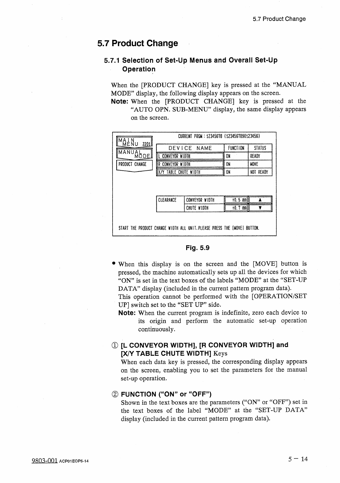
When
the
[
PRODUCT
CHANGE
]
key
is
pressed
at
the
“
MANUAL
MODE
”
display
,
the
following
display
appears
on
the
screen
.
Note
:
When
the
[
PRODUCT
CHANGE
]
key
is
pressed
at
the
“
AUTO
OPN
.
SUB
-
MENU
”
display
,
the
same
display
appears
on
the
screen
.
CURRENT
?
m
:
1234567
B
(
1234567890123456
)
m
N
NU
220
i
STATUS
DEVICE
NAME
FUNCTION
MANUA
Ml
l
CONVEYOR
V
1
DIH
ON
READY
M
|
R
CONVEYOR
yiDTH
PRODUCT
CHANGE
ON
MOVE
IX
/
Y
TABLE
CHilTElM
-
ON
NOT
READY
tQ
.
5
inmll
T
CLEARANCE
CONVEYOR
ViDTH
1
tO
.
7
mj
▼
CHUTE
VIDTH
START
THE
PRODUCT
CHANGE
VIDTH
ALL
UN
IT
,
PLEASE
PRESS
THE
[
MOVE
!
BUTTON
.
Fig
.
5.9
•
When
this
display
is
on
the
screen
and
the
[
MOVE
]
button
is
pressed
,
the
machine
automatically
sets
up
all
the
devices
for
which
“
ON
”
is
set
in
the
text
boxes
of
the
labels
“
MODE
”
at
the
“
SET
-
UP
DATA
”
display
(
included
in
the
current
pattern
program
data
)
.
This
operation
cannot
be
performed
with
the
[
OPERATION
/
SET
UP
]
switch
set
to
the
“
SET
UP
”
side
.
Note
:
When
the
current
program
is
indefinite
,
zero
each
device
to
its
origin
and
perform
the
automatic
set
-
up
operation
continuously
.
①
[
L
CONVEYOR
WIDTH
】
,
[
R
CONVEYOR
WIDTH
]
and
[
X
/
Y
TABLE
CHUTE
WIDTH
]
Keys
When
each
data
key
is
pressed
,
the
corresponding
display
appears
the
screen
,
enabling
you
to
set
the
parameters
for
the
manual
set
-
up
operation
.
on
②
FUNCTION
(
“
ON
”
or
“
OFF
”
)
Shown
in
the
text
boxes
are
the
parameters
(
“
ON
”
or
“
OFF
”
)
set
in
the
text
boxes
of
the
label
“
MODE
”
at
the
“
SET
-
UP
DATA
”
display
(
included
in
the
current
pattern
program
data
)
.
5
一
14
QRQ
^
-
nm
ACP
01
EOP
5
-
14