1OPERATION_.pdf - 第35页
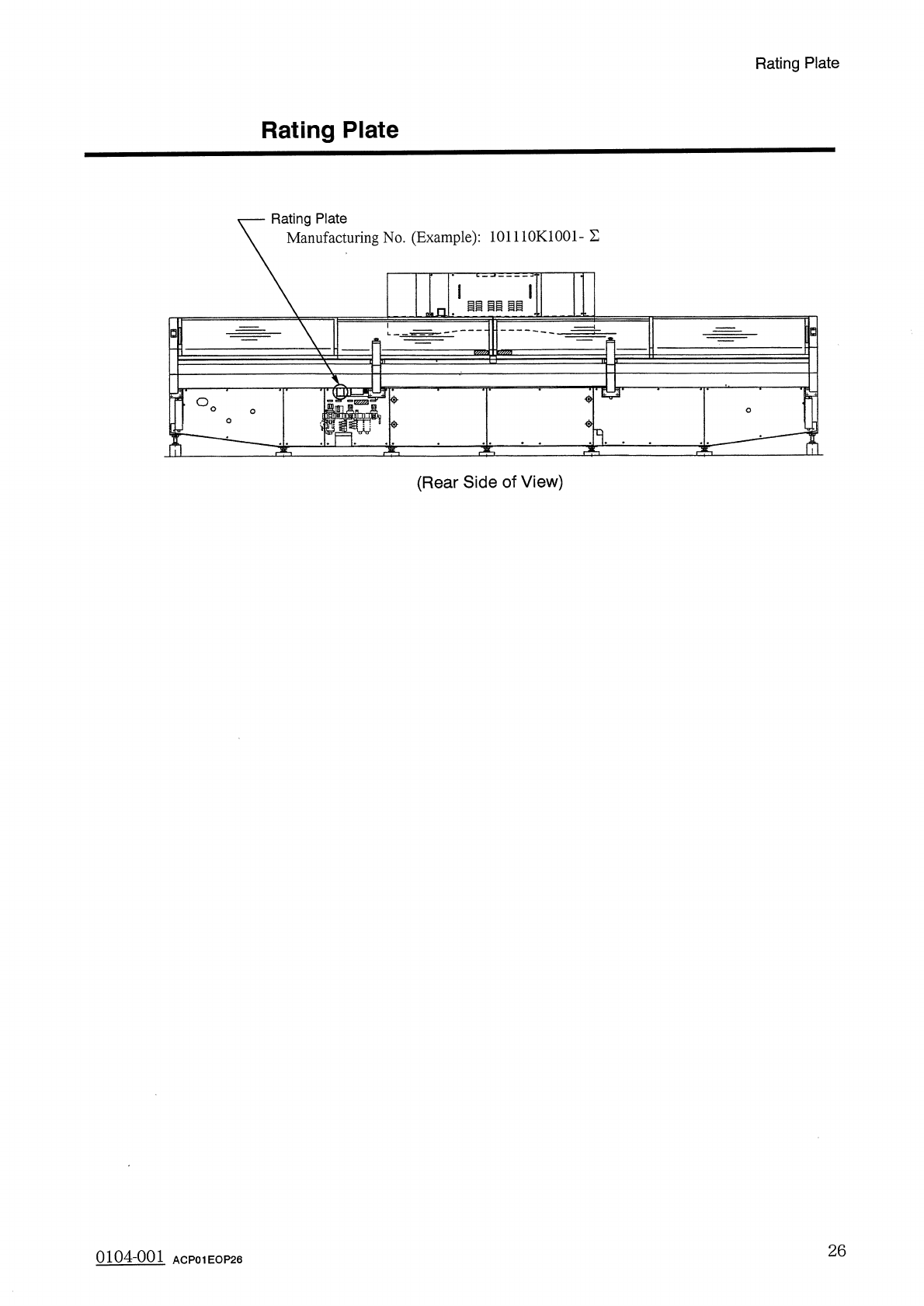
Rating Plate Rating Plate Rating Plate Manufacturing No . ( Example ) : 101110 K 1001 - E ii il m An B < 5 > O iz : $ ( Rear Side of View ) 26 0104 - 001 ACP 01 EOP 26
Module
Protection
Sensor
Module
Protection
Sensor
(
1
)
Tape
Feeder
Mis
-
Set
Detection
Sensor
When
one
of
the
various
proximity
and
limit
switches
is
deactivated
,
the
following
measures
are
taken
to
prevent
relevant
module
from
being
operated
with
a
tape
feeder
set
incorrectly
.
Sensor
Name
Symbol
Countermeasures
Feeder
Mis
-
Set
Template
(
Carriage
#
1
)
Feeder
Mis
-
Set
Template
(
Carriage
#
2
)
Feeder
Mis
-
Set
Bar
Detection
(
Carriage
#
1
)
Feeder
Mis
-
Set
Bar
Detection
(
Carriage
#
2
)
Feeder
Index
Lever
Detection
(
Carriage
#
1
)
Feeder
Index
Lever
Detection
(
Carriage
#
2
)
Feeder
Mis
-
Set
Detection
(
Carriage
#
1
)
Feeder
Mis
-
Set
Detection
(
Carriage
#
2
)
PXS
17
When
one
of
these
switches
is
turned
off
,
the
following
•
Power
to
drive
both
feeder
carriages
#
1
(
FI
:
SMD
2
)
and
#
2
(
F
2
:
SMD
3
)
is
shut
off
.
•
The
rotary
turret
stops
at
0
°
(
rotary
turret
angle
)
.
are
taken
.
measures
PXS
18
LS
5
LS
6
PXS
19
PXS
20
PXS
22
PXS
23
(
2
)
X
/
Y
Table
P
.
C
.
B
.
The
following
describes
what
measures
the
machine
takes
when
a
P
.
C
.
B
.
is
off
-
positioned
operation
.
Detection
Sensor
the
X
/
Y
table
during
placement
on
Sensor
Name
Countermeasures
Symbol
X
/
Y
Table
P
.
C
.
B
.
Detection
(
Fixed
)
X
/
Y
Table
P
.
C
.
B
.
Detection
(
Movable
)
When
one
of
these
photoswitches
is
turned
off
,
the
following
•
Power
to
drive
the
X
/
Y
table
(
X
:
SMD
4
,
Y
:
SMD
5
)
is
shut
off
.
•
The
rotary
turret
stops
at
0
°
(
rotary
turret
angle
)
.
PHS
55
PHS
56
are
taken
.
measures
(
3
)
Feeder
Carriage
Collision
Detection
Sensor
Sensor
Name
Countermeasures
Symbol
Feeder
Carriage
Collision
Detection
•
Power
to
drive
both
feeder
carriages
#
1
(
FI
:
SMD
2
)
and
#
2
(
F
2
:
SMD
3
)
is
shut
off
.
•
The
rotary
turret
stops
at
0
°
(
rotary
turret
angle
)
.
PHS
63
mn
4
-
nm
25
ACP
01
EOP
25
Rating
Plate
Rating
Plate
Rating
Plate
Manufacturing
No
.
(
Example
)
:
101110
K
1001
-
E
ii
il
m
An
B
<
5
>
O
iz
:
$
(
Rear
Side
of
View
)
26
0104
-
001
ACP
01
EOP
26
娜 灌
1
…
.
Page
1.1
Scope
1.2
Specifications
1.3
Structure
and
Names
1.4
Operation
Panel
1.4
.
1
Power
Breaker
Crank
1.4
.
2
Front
Operation
Panel
1.4
.
3
Rear
Operation
Panel
1.4
.
4
Front
Console
Panel
1.4
.
5
Rear
Console
Panel
1.4
.
6
[
C
1
READY
]
and
[
C
2
READY
]
Buttons
1.5
Scope
of
Actions
1.5
.
1
P
.
C
.
B
.
Transfer
1.5
.
2
Component
Placement
Section
1.6
Construction
of
Feeder
Carriages
•
•
•
1.7
Installation
of
Tape
Feeders
on
Feeder
Carriages
1.8
Placement
Head
Section
1.9
List
of
Nozzle
Types
1.10
[
PNL
CHANGE
]
Buttons
1.11
[
OPERATION
]
Switch
1.12
Recognition
Monitor
1
1
-
17
1
-
18
1
-
18
1
-
20
1
-
23
1
-
26
1
-
28
1
-
30
1
-
31
1
-
31
1
-
32
1
-
35
1
-
36
1
-
39
1
-
41
1
-
44
1
-
46
1
-
47
9803
-
001
ACP
01
EOPCC
1