1OPERATION_.pdf - 第42页
1.2 Specifications 10 . Number of Installable Tape Feeders Max . 160 feeders ( The above number of feeders are determined assuming that only 8 mm tape and hopper - type bulk feeders are used . ) Max . 160 feeders only wh…
1.2
Specifications
9
.
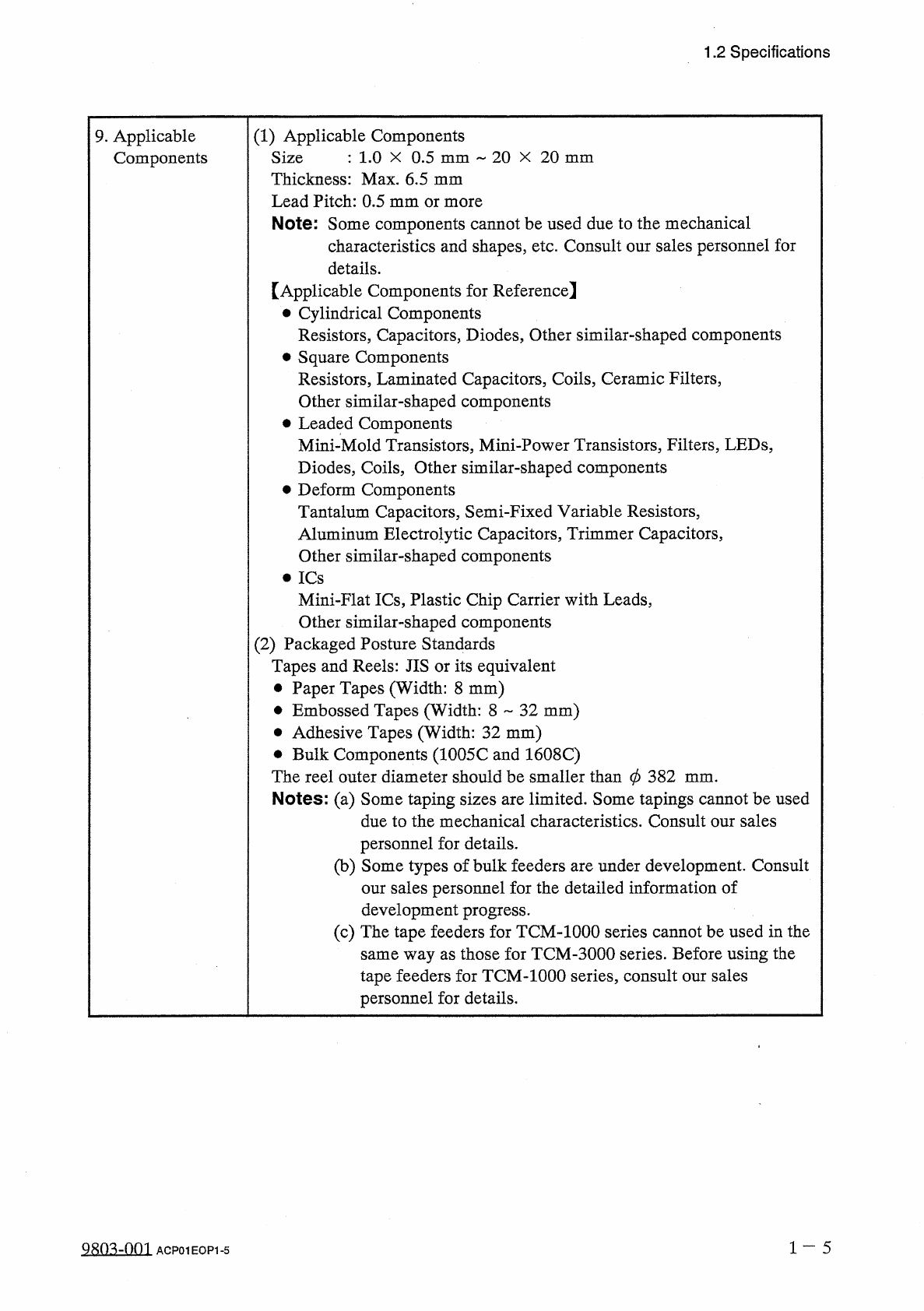
Applicable
Components
(
1
)
Applicable
Components
:
1.0
X
0.5
mm
20
X
20
mm
Size
Thickness
:
Max
.
6.5
mm
Lead
Pitch
:
0.5
mm
or
more
Note
:
Some
components
cannot
be
used
due
to
the
mechanical
characteristics
and
shapes
,
etc
.
Consult
our
sales
personnel
for
details
.
【
Applicable
Components
for
Reference
】
•
Cylindrical
Components
Resistors
,
Capacitors
,
Diodes
,
Other
similar
-
shaped
components
•
Square
Components
Resistors
,
Laminated
Capacitors
,
Coils
,
Ceramic
Filters
,
Other
similar
-
shaped
components
•
Leaded
Components
Mini
-
Mold
Transistors
,
Mini
-
Power
Transistors
,
Filters
,
LEDs
,
Diodes
,
Coils
,
Other
similar
-
shaped
components
•
Deform
Components
Tantalum
Capacitors
,
Semi
-
Fixed
Variable
Resistors
,
Aluminum
Electrolytic
Capacitors
,
Trimmer
Capacitors
,
Other
similar
-
shaped
components
•
ICs
Mini
-
Flat
ICs
,
Plastic
Chip
Carrier
with
Leads
,
Other
similar
-
shaped
components
(
2
)
Packaged
Posture
Standards
Tapes
and
Reels
:
JIS
or
its
equivalent
•
Paper
Tapes
(
Width
:
8
mm
)
•
Embossed
Tapes
(
Width
:
8
-
32
mm
)
•
Adhesive
Tapes
(
Width
:
32
mm
)
•
Bulk
Components
(
1005
C
and
1608
C
)
The
reel
outer
diameter
should
be
smaller
than
0
382
Notes
:
(
a
)
Some
taping
sizes
are
limited
.
Some
tapings
cannot
be
used
due
to
the
mechanical
characteristics
.
Consult
our
sales
personnel
for
details
.
(
b
)
Some
types
of
bulk
feeders
are
under
development
.
Consult
our
sales
personnel
for
the
detailed
information
of
development
progress
.
(
c
)
The
tape
feeders
for
TCM
-
1000
series
cannot
be
used
in
the
same
way
as
those
for
TCM
-
3000
series
.
Before
using
the
tape
feeders
for
TCM
-
1000
series
,
consult
our
sales
personnel
for
details
.
mm
.
1
一
5
Q
80
^
-
nm
ACP
01
EOP
1
-
5
1.2
Specifications
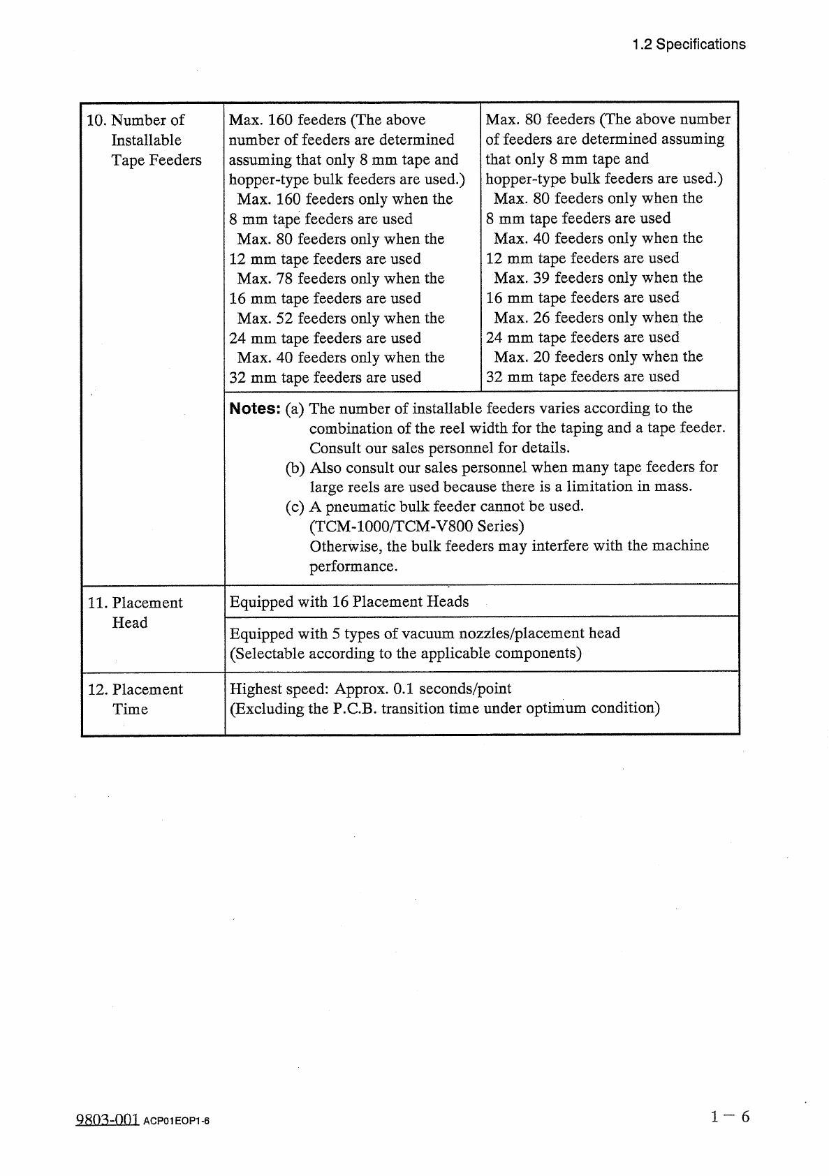
10
.
Number
of
Installable
Tape
Feeders
Max
.
160
feeders
(
The
above
number
of
feeders
are
determined
assuming
that
only
8
mm
tape
and
hopper
-
type
bulk
feeders
are
used
.
)
Max
.
160
feeders
only
when
the
8
mm
tape
feeders
are
used
Max
.
80
feeders
only
when
the
12
mm
tape
feeders
are
used
Max
.
78
feeders
only
when
the
16
mm
tape
feeders
are
used
Max
.
52
feeders
only
when
the
24
mm
tape
feeders
are
used
Max
.
40
feeders
only
when
the
32
mm
tape
feeders
are
used
Max
.
80
feeders
(
The
above
number
of
feeders
are
determined
assuming
that
only
8
mm
tape
and
hopper
-
type
bulk
feeders
are
used
.
)
Max
.
80
feeders
only
when
the
8
mm
tape
feeders
are
used
Max
.
40
feeders
only
when
the
12
mm
tape
feeders
are
used
Max
.
39
feeders
only
when
the
16
mm
tape
feeders
are
used
Max
.
26
feeders
only
when
the
24
mm
tape
feeders
are
used
Max
.
20
feeders
only
when
the
32
mm
tape
feeders
are
used
Notes
:
(
a
)
The
number
of
installable
feeders
varies
according
to
the
combination
of
the
reel
width
for
the
taping
and
a
tape
feeder
.
Consult
our
sales
personnel
for
details
.
(
b
)
Also
consult
our
sales
personnel
when
many
tape
feeders
for
large
reels
are
used
because
there
is
a
limitation
in
mass
.
(
c
)
A
pneumatic
bulk
feeder
cannot
be
used
.
(
TCM
-
1000
/
TCM
-
V
800
Series
)
Otherwise
,
the
bulk
feeders
may
interfere
with
the
machine
performance
.
Equipped
with
16
Placement
Heads
11
.
Placement
Head
Equipped
with
5
types
of
vacuum
nozzles
/
placement
head
(
Selectable
according
to
the
applicable
components
)
Highest
speed
:
Approx
.
0.1
seconds
/
point
(
Excluding
the
P
.
C
.
B
.
transition
time
under
optimum
condition
)
12
.
Placement
Time
1
一
6
Q
80
^
-
0
f
)
1
ACP
01
EOP
1
-
6
1.2
Specifications
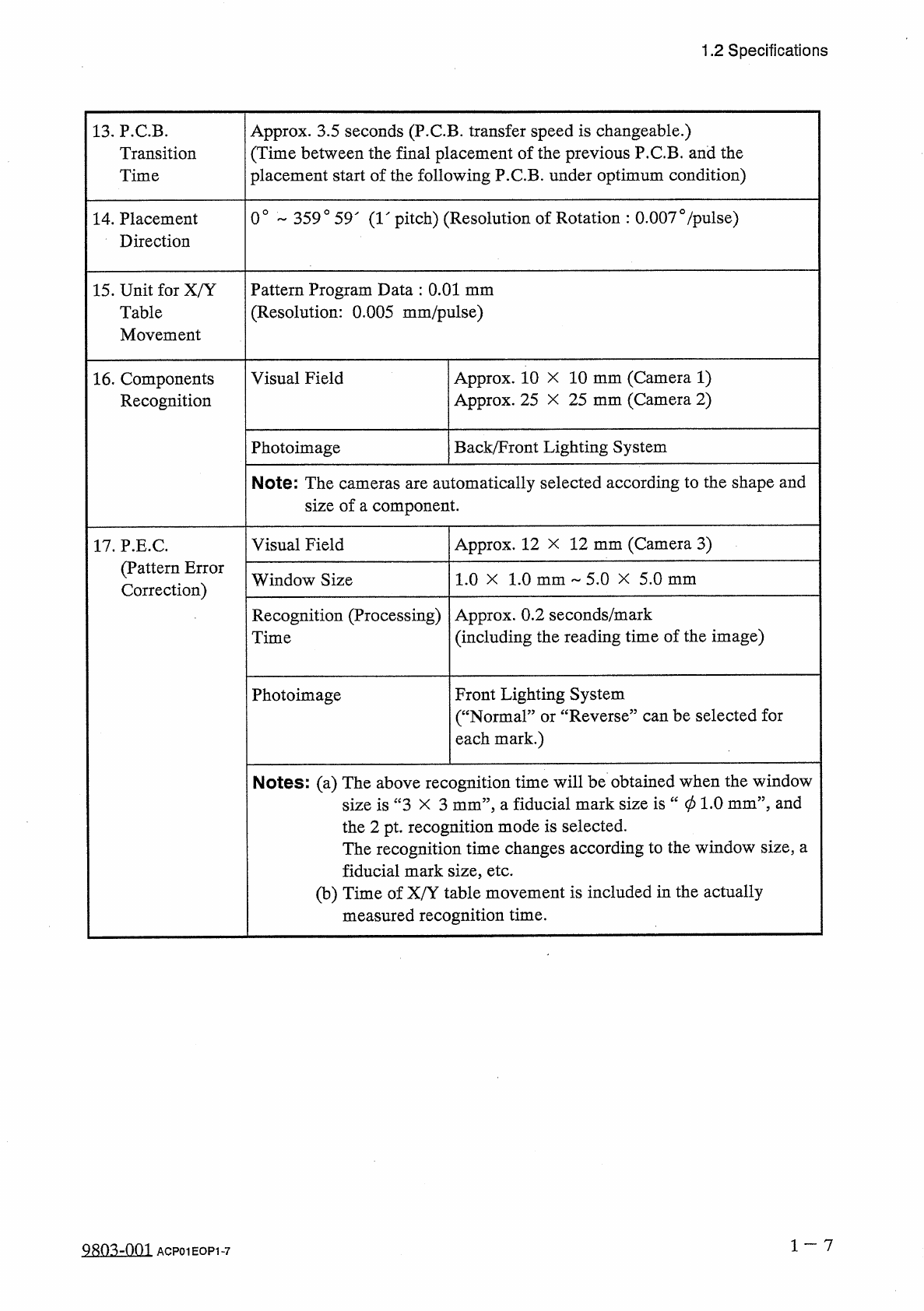
13
.
P
.
CB
.
Transition
Time
Approx
.
3.5
seconds
(
P
.
CB
.
transfer
speed
is
changeable
.
)
(
Time
between
the
final
placement
of
the
previous
P
.
C
.
B
.
and
the
placement
start
of
the
following
P
.
CB
.
under
optimum
condition
)
0
°
359
°
59
"
(
1
"
pitch
)
(
Resolution
of
Rotation
:
0.0070
/
pulse
)
14
.
Placement
Direction
15
.
Unit
for
X
/
Y
Table
Movement
Pattern
Program
Data
:
0.01
mm
(
Resolution
:
0.005
mm
/
pulse
)
Visual
Field
Approx
.
10
X
10
mm
(
Camera
1
)
Approx
.
25
X
25
mm
(
Camera
2
)
16
.
Components
Recognition
Photoimage
Back
/
Front
Lighting
System
Note
:
The
cameras
are
automatically
selected
according
to
the
shape
and
size
of
a
component
.
Visual
Field
Approx
.
12
X
12
mm
(
Camera
3
)
17
.
P
.
E
.
C
.
(
Pattern
Error
Correction
)
Window
Size
1.0
X
1.0
mm
-
5.0
X
5.0
mm
Recognition
(
Processing
)
Time
Approx
.
0.2
seconds
/
mark
(
including
the
reading
time
of
the
image
)
Photoimage
Front
Lighting
System
(
“
Normal
”
or
“
Reverse
”
can
be
selected
for
each
mark
.
)
Notes
:
(
a
)
The
above
recognition
time
will
be
obtained
when
the
window
size
is
“
3
X
3
mm
’
’
,
a
fiducial
mark
size
is
“
01.0
mm
”
5
and
the
2
pt
.
recognition
mode
is
selected
.
The
recognition
time
changes
according
to
the
window
size
,
a
fiducial
mark
size
,
etc
.
(
b
)
Time
of
X
/
Y
table
movement
is
included
in
the
actually
measured
recognition
time
.
1
一
7
9803
-
001
ACP
01
EOP
1
-
7