1OPERATION_.pdf - 第45页
1.2 Specifications 19 . Setting of Fiducial Mark P . E . C . Recognition • Two or three fiducial marks ( two fiducial marks required for each unit P . C . B . of a multi - unit P . C . B . ) are put on the selected posit…
1.2
Specifications
•
o
■
口
▲
厶
+
■
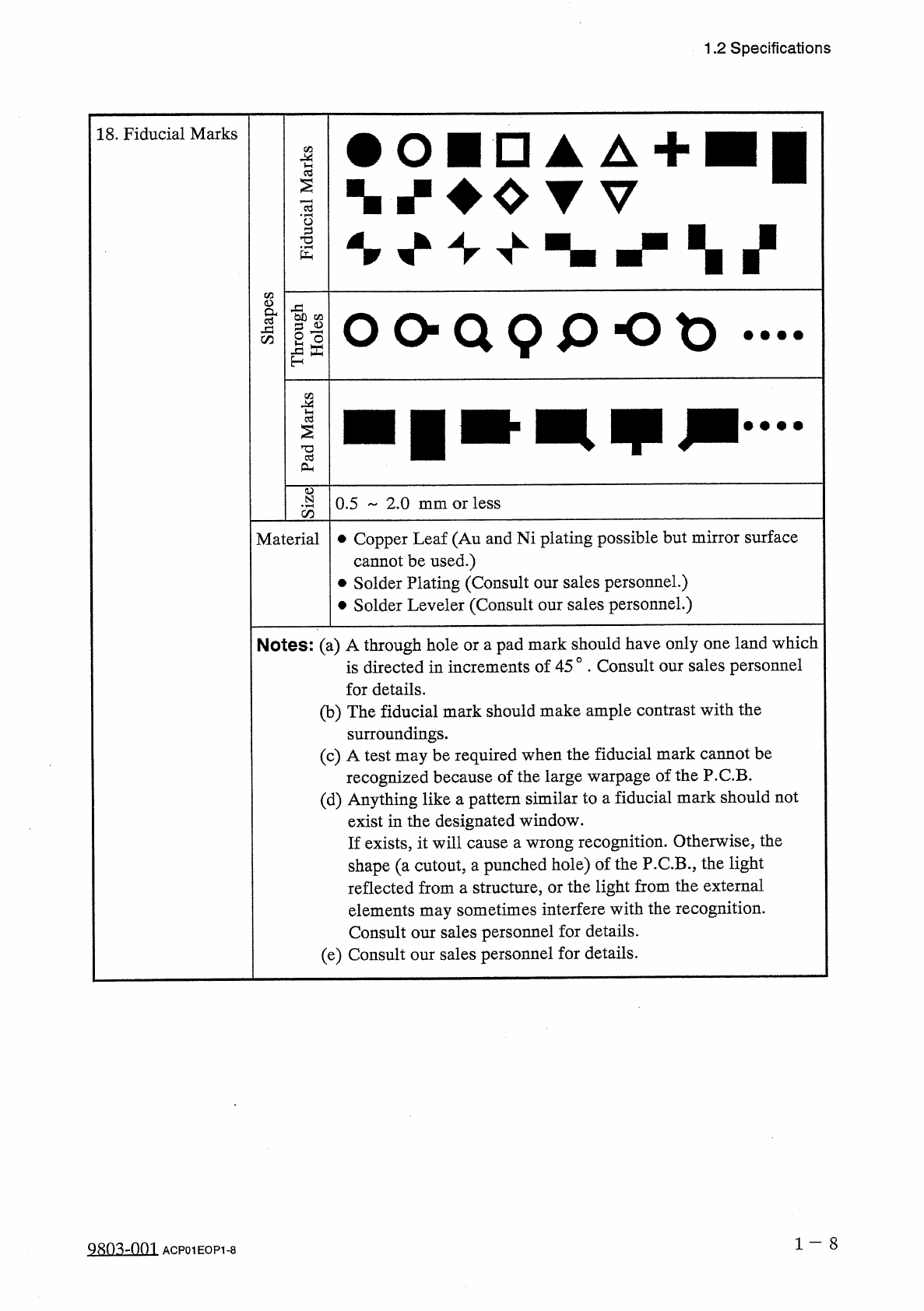
18
.
Fiducial
Marks
|
1
O
O
Q
9
p
O
t
)
•
•
•
•
0.5
2.0
mm
or
less
Material
•
Copper
Leaf
(
Au
and
Ni
plating
possible
but
mirror
surface
cannot
be
used
.
)
•
Solder
Plating
(
Consult
our
sales
personnel
.
)
•
Solder
Leveler
(
Consult
our
sales
personnel
.
)
Notes
:
(
a
)
A
through
hole
or
a
pad
mark
should
have
only
one
land
which
is
directed
in
increments
of
45
°
.
Consult
our
sales
personnel
for
details
.
(
b
)
The
fiducial
mark
should
make
ample
contrast
with
the
surroundings
.
(
c
)
A
test
may
be
required
when
the
fiducial
mark
recognized
because
of
the
large
warpage
of
the
(
d
)
Anything
like
a
pattern
similar
to
a
exist
in
the
designated
window
.
If
exists
,
it
will
cause
a
wrong
recognition
.
Otherwise
,
the
shape
(
a
cutout
,
a
punched
hole
)
of
the
P
.
C
.
B
.
,
the
light
reflected
from
a
structure
,
or
the
light
from
the
external
elements
may
sometimes
interfere
with
the
recognition
.
Consult
our
sales
personnel
for
details
.
(
e
)
Consult
our
sales
personnel
for
details
.
be
cannot
P
.
C
.
B
.
fiducial
mark
should
not
1
-
8
Q
803
-
nm
ACP
01
EOP
1
-
8
ucdld
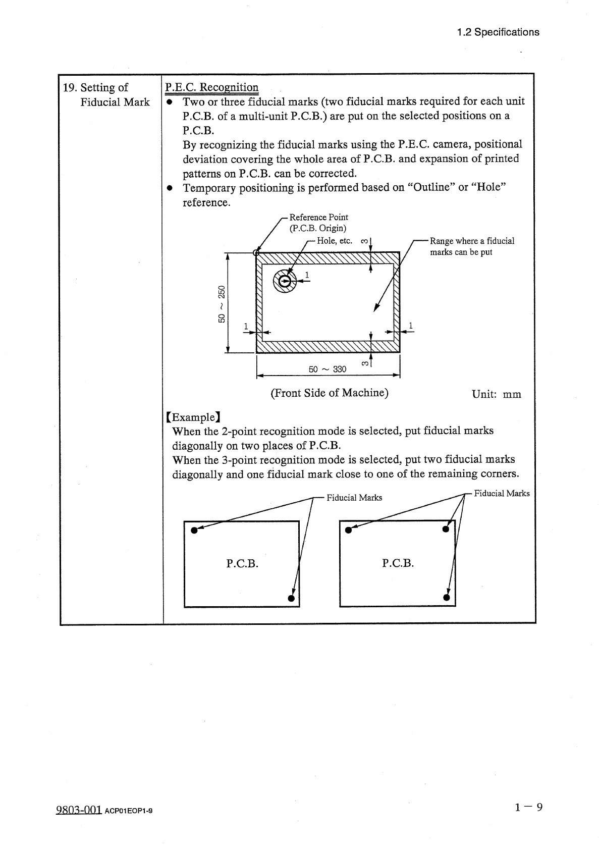
1.2
Specifications
19
.
Setting
of
Fiducial
Mark
P
.
E
.
C
.
Recognition
•
Two
or
three
fiducial
marks
(
two
fiducial
marks
required
for
each
unit
P
.
C
.
B
.
of
a
multi
-
unit
P
.
C
.
B
.
)
are
put
on
the
selected
positions
on
a
P
.
C
.
B
.
By
recognizing
the
fiducial
marks
using
the
P
.
E
.
C
.
camera
,
positional
deviation
covering
the
whole
area
of
P
.
C
.
B
.
and
expansion
of
printed
patterns
on
P
.
C
.
B
.
can
be
corrected
.
•
Temporary
positioning
is
performed
based
on
“
Outline
”
or
“
Hole
”
reference
.
Reference
Point
(
P
.
C
.
B
.
Origin
)
Hole
,
etc
.
Range
where
a
fiducial
marks
can
be
put
co
l
8
CO
50
330
(
Front
Side
of
Machine
)
Unit
:
mm
【
Example
】
When
the
2
-
point
recognition
mode
is
selected
,
put
fiducial
marks
diagonally
on
two
places
of
P
.
C
.
B
.
When
the
3
-
point
recognition
mode
is
selected
,
put
two
fiducial
marks
diagonally
and
one
fiducial
mark
close
to
one
of
the
remaining
corners
.
Fiducial
Marks
Fiducial
Marks
1
一
9
Q
80
^
-
nm
ACP
01
EOP
1
-
9
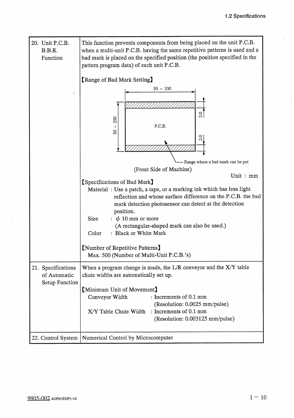
1.2
Specifications
This
function
prevents
components
from
being
placed
on
the
unit
P
.
C
.
B
.
when
a
multi
-
unit
P
.
C
.
B
.
having
the
same
repetitive
patterns
is
used
and
a
bad
mark
is
placed
on
the
specified
position
(
the
position
specified
in
the
pattern
program
data
)
of
each
unit
P
.
C
.
B
.
20
.
UnitP
.
CB
.
B
.
B
.
R
.
Function
[
Range
of
Bad
Mark
Setting
]
50
330
y
/
/
/
/
/
/
/
/
/
/
/
/
/
/
/
/
/
/
/
/
/
/
/
z
P
.
C
.
B
.
-
A
.
Range
where
a
bad
mark
can
be
put
(
Front
Side
of
Machine
)
Unit
:
mm
[
Specifications
of
Bad
Mark
】
Material
:
Use
a
patch
,
a
tape
,
or
a
marking
ink
which
has
less
light
reflection
and
whose
surface
difference
on
the
P
.
C
.
B
.
the
bad
mark
detection
photosensor
can
detect
at
the
detection
position
.
:
0
10
mm
or
more
(
A
rectangular
-
shaped
mark
can
also
be
used
.
)
:
Black
or
White
Mark
Size
Color
【
Number
of
Repetitive
Patterns
]
Max
.
500
(
Number
of
Multi
-
Unit
P
.
C
.
B
.
’
s
)
21
.
Specifications
of
Automatic
Setup
Function
When
a
program
change
is
made
,
the
L
/
R
conveyor
and
the
X
/
Y
table
chute
widths
are
automatically
set
up
.
[
Minimum
Unit
of
Movement
]
Conveyor
Width
:
Increments
of
0.1
mm
(
Resolution
:
0.0025
mm
/
pulse
)
X
/
Y
Table
Chute
Width
:
Increments
of
0.1
mm
(
Resolution
:
0.003125
mm
/
pulse
)
Numerical
Control
by
Microcomputer
22
.
Control
System
1
-
1 0
9905
-
002
ACPOIEOPI
-
IO