1OPERATION_.pdf - 第54页
1.4 Operation Panel 1.4 Operation Panel 1.4 . 1 Power Breaker Crank The power breaker crank can be locked using a padlock . Before performing maintenance and inspections work , shut off the power breaker and lock it usin…
1.3
Structure
and
Names
1.3
Structure
and
Names
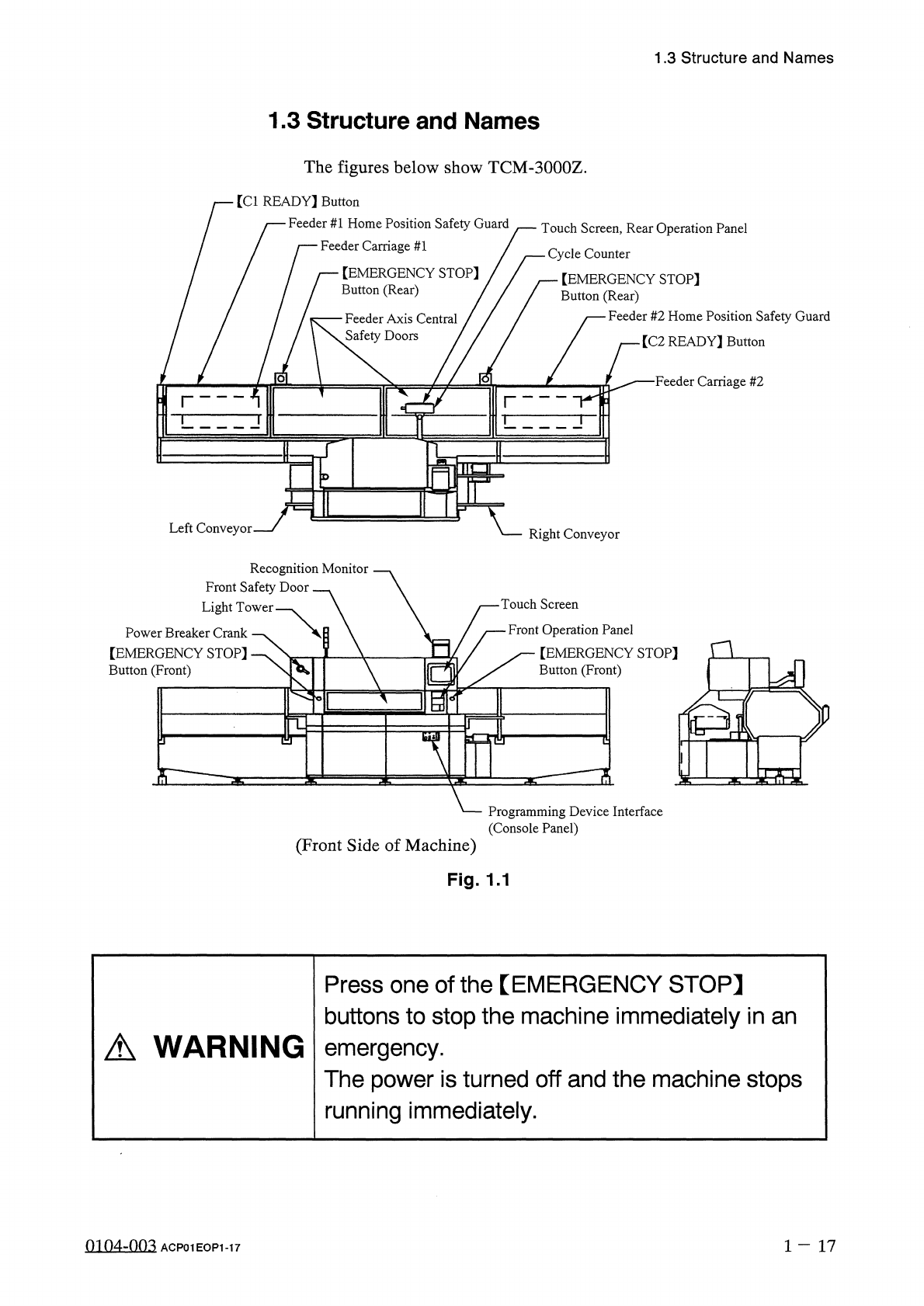
The
figures
below
show
TCM
-
3000
Z
.
[
Cl
READY
】
Button
Feeder
#
1
Home
Position
Safety
Guard
Feeder
Carriage
#
1
/
Touch
Screen
,
Rear
Operation
Panel
一
Cycle
Counter
【
EMERGENCY
STOP
]
Button
(
Rear
)
【
EMERGENCY
STOP
]
Button
(
Rear
)
Feeder
#
2
Home
Position
Safety
Guard
Feeder
Axis
Central
Safety
Doors
/
[
C
2
READY
]
Button
■
Feeder
Carriage
#
2
o
Left
Conveyor
Right
Conveyor
Recognition
Monitor
Front
Safety
Door
Light
Tower
Touch
Screen
Front
Operation
Panel
[
EMERGENCY
STOP
]
Button
(
Front
)
Power
Breaker
Crank
【
EMERGENCY
STOP
]
Button
(
Front
)
n
a
%
-
^
?
i
S
:
Programming
Device
Interface
(
Console
Panel
)
(
Front
Side
of
Machine
)
Fig
.
1.1
Press
one
of
the
【
EMERGENCY
STOP
】
buttons
to
stop
the
machine
immediately
in
an
emergency
.
The
power
is
turned
off
and
the
machine
stops
running
immediately
.
A
WARNING
0104
-
003
1
-
17
ACP
01
EOP
1
-
17
1.4
Operation
Panel
1.4
Operation
Panel
1.4
.
1
Power
Breaker
Crank
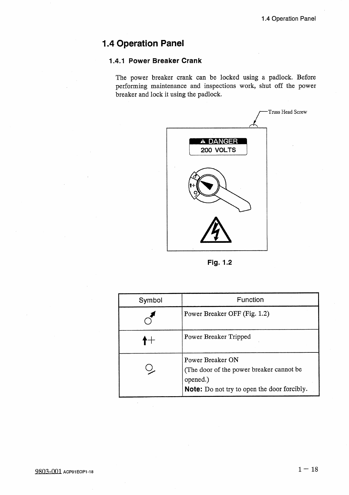
The
power
breaker
crank
can
be
locked
using
a
padlock
.
Before
performing
maintenance
and
inspections
work
,
shut
off
the
power
breaker
and
lock
it
using
the
padlock
.
Truss
Head
Screw
Fig
.
1.2
Symbol
Function
Power
Breaker
OFF
(
Fig
.
1.2
)
Power
Breaker
Tripped
t
+
Power
Breaker
ON
(
The
door
of
the
power
breaker
cannot
be
opened
.
)
Note
:
Do
not
try
to
open
the
door
forcibly
.
1
一
18
Q
803
-
0
m
ACP
01
EOP
1
-
18
1.4
Operation
Panel
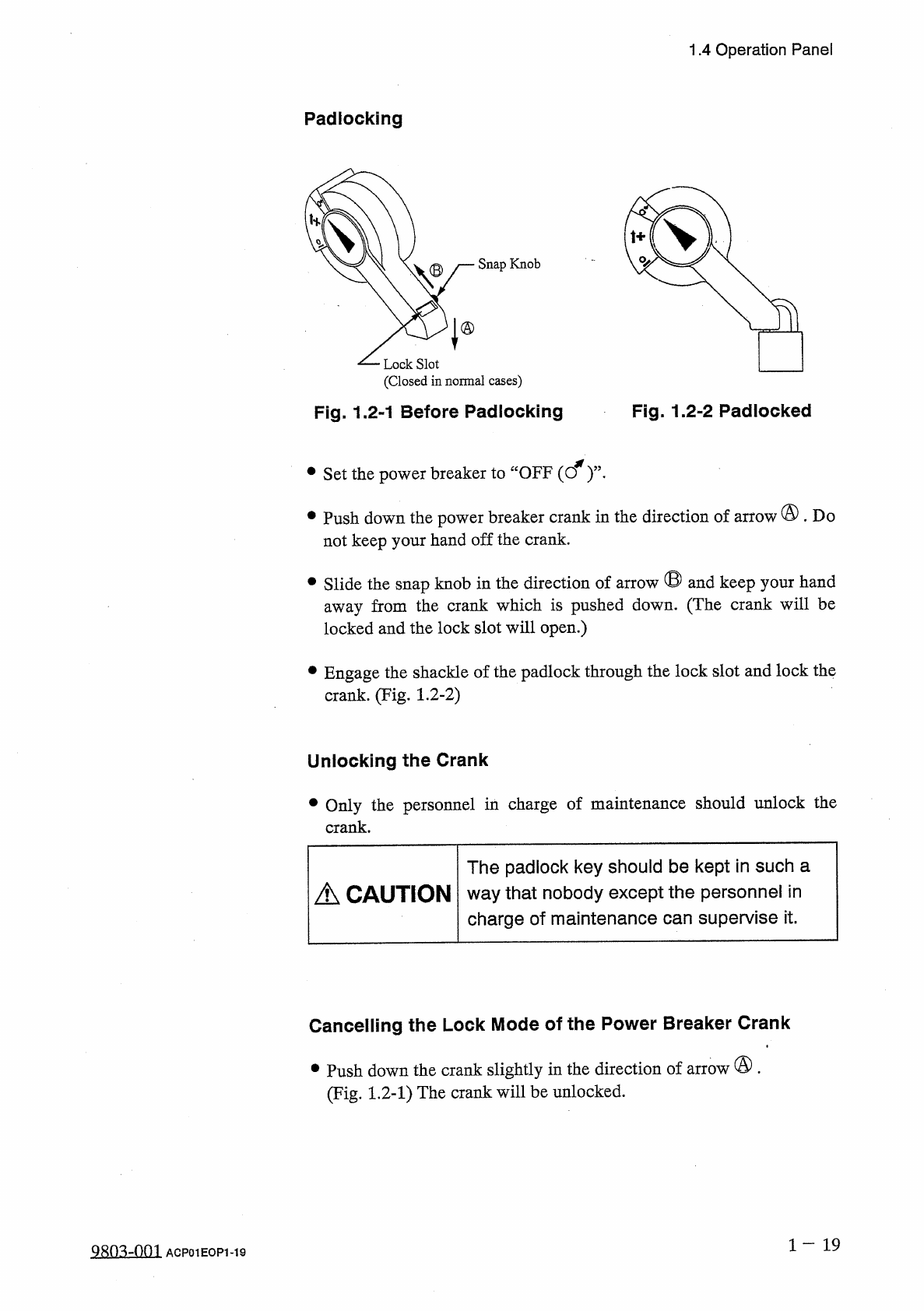
Padlocking
Snap
Knob
Lock
Slot
(
Closed
in
normal
cases
)
Fig
.
1.2
-
1
Before
Padlocking
Fig
.
1.2
-
2
Padlocked
•
Set
the
power
breaker
to
“
OFF
(
cf
)
’
’
•
•
Push
down
the
power
breaker
crank
in
the
direction
of
arrow
@
.
Do
not
keep
your
hand
off
the
crank
.
•
Slide
the
snap
knob
in
the
direction
of
arrow
®
and
keep
your
hand
away
from
the
crank
which
is
pushed
down
.
(
The
crank
will
be
locked
and
the
lock
slot
will
open
.
)
•
Engage
the
shackle
of
the
padlock
through
the
lock
slot
and
lock
the
crank
.
(
Fig
.
1.2
-
2
)
Unlocking
the
Crank
•
Only
the
personnel
in
charge
of
maintenance
should
unlock
the
crank
.
The
padlock
key
should
be
kept
in
such
a
way
that
nobody
except
the
personnel
in
charge
of
maintenance
can
supervise
it
.
A
CAUTION
Cancelling
the
Lock
Mode
of
the
Power
Breaker
Crank
•
Push
down
the
crank
slightly
in
the
direction
of
arrow
®
.
(
Fig
.
1.2
-
1
)
The
crank
will
be
unlocked
.
1
-
19
9
Sn
^
-
001
ACP
01
EOP
1
-
19