1OPERATION_.pdf - 第55页
1.4 Operation Panel Padlocking Snap Knob Lock Slot ( Closed in normal cases ) Fig . 1.2 - 1 Before Padlocking Fig . 1.2 - 2 Padlocked • Set the power breaker to “ OFF ( cf ) ’ ’ • • Push down the power breaker crank in t…
1.4
Operation
Panel
1.4
Operation
Panel
1.4
.
1
Power
Breaker
Crank
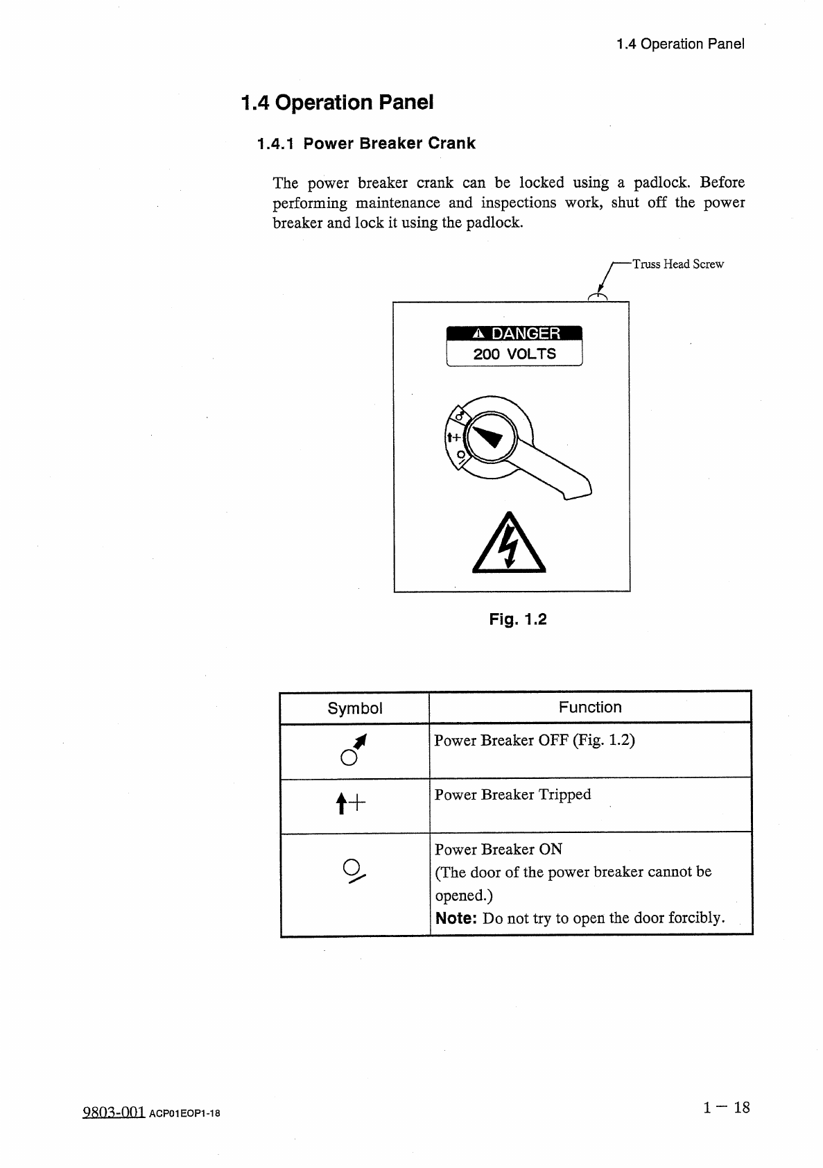
The
power
breaker
crank
can
be
locked
using
a
padlock
.
Before
performing
maintenance
and
inspections
work
,
shut
off
the
power
breaker
and
lock
it
using
the
padlock
.
Truss
Head
Screw
Fig
.
1.2
Symbol
Function
Power
Breaker
OFF
(
Fig
.
1.2
)
Power
Breaker
Tripped
t
+
Power
Breaker
ON
(
The
door
of
the
power
breaker
cannot
be
opened
.
)
Note
:
Do
not
try
to
open
the
door
forcibly
.
1
一
18
Q
803
-
0
m
ACP
01
EOP
1
-
18
1.4
Operation
Panel
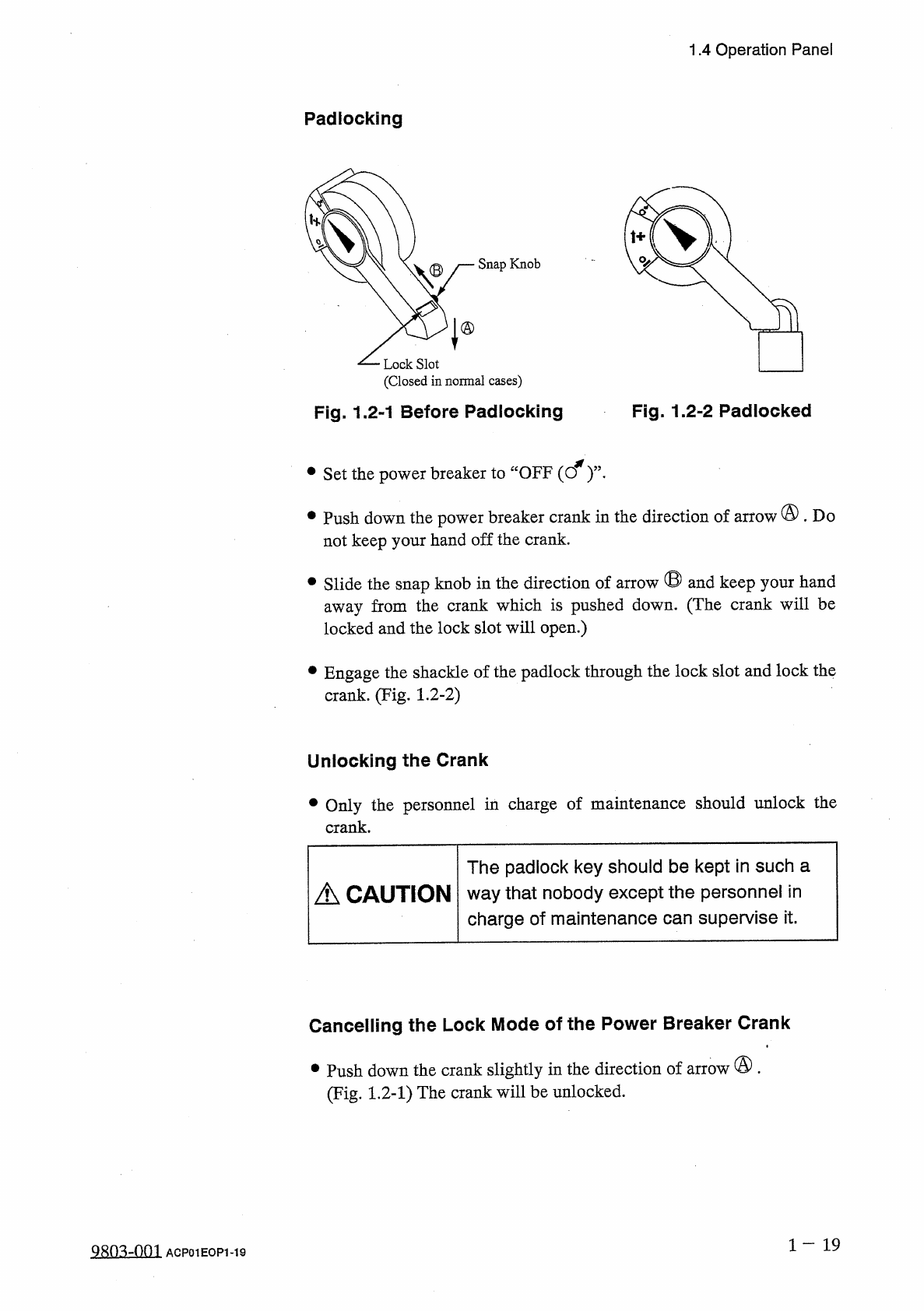
Padlocking
Snap
Knob
Lock
Slot
(
Closed
in
normal
cases
)
Fig
.
1.2
-
1
Before
Padlocking
Fig
.
1.2
-
2
Padlocked
•
Set
the
power
breaker
to
“
OFF
(
cf
)
’
’
•
•
Push
down
the
power
breaker
crank
in
the
direction
of
arrow
@
.
Do
not
keep
your
hand
off
the
crank
.
•
Slide
the
snap
knob
in
the
direction
of
arrow
®
and
keep
your
hand
away
from
the
crank
which
is
pushed
down
.
(
The
crank
will
be
locked
and
the
lock
slot
will
open
.
)
•
Engage
the
shackle
of
the
padlock
through
the
lock
slot
and
lock
the
crank
.
(
Fig
.
1.2
-
2
)
Unlocking
the
Crank
•
Only
the
personnel
in
charge
of
maintenance
should
unlock
the
crank
.
The
padlock
key
should
be
kept
in
such
a
way
that
nobody
except
the
personnel
in
charge
of
maintenance
can
supervise
it
.
A
CAUTION
Cancelling
the
Lock
Mode
of
the
Power
Breaker
Crank
•
Push
down
the
crank
slightly
in
the
direction
of
arrow
®
.
(
Fig
.
1.2
-
1
)
The
crank
will
be
unlocked
.
1
-
19
9
Sn
^
-
001
ACP
01
EOP
1
-
19
1.4
Operation
Panel
1.4
.
2
Front
Operation
Panel
入
操 作
□
夕
LOCK
ON
o
LED
7
PB
1
(
LED
1
)
、
:
亍厶夕
U
7
SYS
/
CLR
前後操作切替
PNL
CHANGE
運転乇一卜
,
OPERATION
段取
SET
UP
-
贿止
PAUSE
始動
停止
START
STOP
PB
8
PB
7
PB
5
(
LED
2
)
復帰
RESET
BZ
1
(
(
o
>
)
PB
9
全原点復帰
ZERO
基板移载
TRANSFER
働
MOVE
PB
12
PB
11
PB
6
(
LED
3
) (
LED
4
)
(
LED
5
)
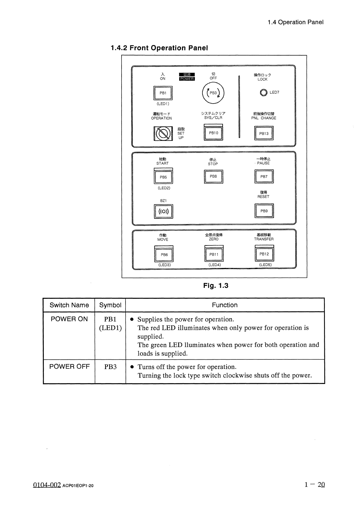
Fig
.
1.3
Symbol
Switch
Name
Function
POWER
ON
•
Supplies
the
power
for
operation
.
The
red
LED
illuminates
when
only
power
for
operation
is
supplied
.
The
green
LED
lluminates
when
power
for
both
operation
and
loads
is
supplied
.
PB
1
(
LED
1
)
POWER
OFF
•
Turns
off
the
power
for
operation
.
Turning
the
lock
type
switch
clockwise
shuts
off
the
power
.
PB
3
1
-
2
Q
0104
-
002
ACP
01
EOP
1
-
20