1OPERATION_.pdf - 第57页
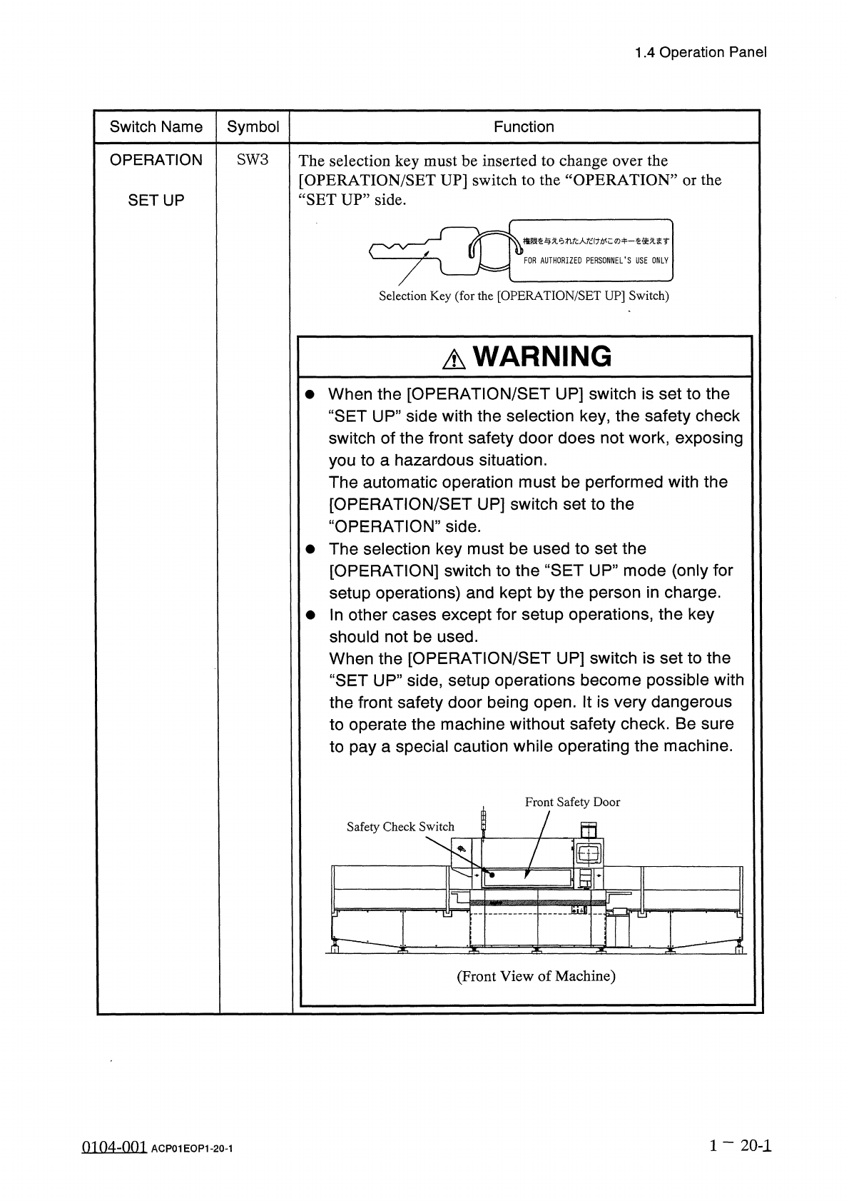
1.4 Operation Panel Switch Name Symbol Function OPERATION SW 3 The selection key must be inserted to change over the [ OPERATION / SET UP ] switch to the “ OPERATION ” or the “ SET UP ” side . SETUP 梅限汔与 xemfc 人纪 f : wc …
1.4
Operation
Panel
1.4
.
2
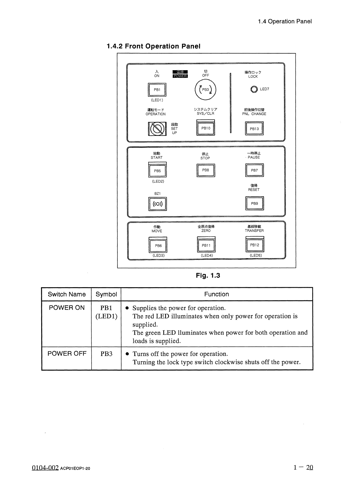
Front
Operation
Panel
入
操 作
□
夕
LOCK
ON
o
LED
7
PB
1
(
LED
1
)
、
:
亍厶夕
U
7
SYS
/
CLR
前後操作切替
PNL
CHANGE
運転乇一卜
,
OPERATION
段取
SET
UP
-
贿止
PAUSE
始動
停止
START
STOP
PB
8
PB
7
PB
5
(
LED
2
)
復帰
RESET
BZ
1
(
(
o
>
)
PB
9
全原点復帰
ZERO
基板移载
TRANSFER
働
MOVE
PB
12
PB
11
PB
6
(
LED
3
) (
LED
4
)
(
LED
5
)
Fig
.
1.3
Symbol
Switch
Name
Function
POWER
ON
•
Supplies
the
power
for
operation
.
The
red
LED
illuminates
when
only
power
for
operation
is
supplied
.
The
green
LED
lluminates
when
power
for
both
operation
and
loads
is
supplied
.
PB
1
(
LED
1
)
POWER
OFF
•
Turns
off
the
power
for
operation
.
Turning
the
lock
type
switch
clockwise
shuts
off
the
power
.
PB
3
1
-
2
Q
0104
-
002
ACP
01
EOP
1
-
20
1.4
Operation
Panel
Switch
Name
Symbol
Function
OPERATION
SW
3
The
selection
key
must
be
inserted
to
change
over
the
[
OPERATION
/
SET
UP
]
switch
to
the
“
OPERATION
”
or
the
“
SET
UP
”
side
.
SETUP
梅限汔与
xemfc
人纪
f
:
wc
:
ro
+
_
汔使无圭
r
FOR
AUTHORIZED
PERSONNEL
’
S
USE
ONLY
Selection
Key
(
for
the
[
OPERATION
/
SET
UP
]
Switch
)
A
WARNING
•
When
the
[
OPERATION
/
SET
UP
]
switch
is
set
to
the
“
SET
UP
”
side
with
the
selection
key
,
the
safety
check
switch
of
the
front
safety
door
does
not
work
,
exposing
you
to
a
hazardous
situation
.
The
automatic
operation
must
be
performed
with
the
[
OPERATION
/
SET
UP
]
switch
set
to
the
“
OPERATION
”
side
.
•
The
selection
key
must
be
used
to
set
the
[
OPERATION
]
switch
to
the
“
SET
UP
”
mode
(
only
for
setup
operations
)
and
kept
by
the
person
in
charge
.
•
In
other
cases
except
for
setup
operations
,
the
key
should
not
be
used
.
When
the
[
OPERATION
/
SET
UP
]
switch
is
set
to
the
“
SET
UP
”
side
,
setup
operations
become
possible
with
the
front
safety
door
being
open
.
It
is
very
dangerous
to
operate
the
machine
without
safety
check
.
Be
sure
to
pay
a
special
caution
while
operating
the
machine
.
Front
Safety
Door
Safety
Check
Switch
5
画
10
;
mr
7
T
—
^
-
(
Front
View
of
Machine
)
1
一
20
-
1
0104
-
001
ACP
01
EOP
1
-
20
-
1
1.4
Operation
Panel
Switch
Name
Symbol
Function
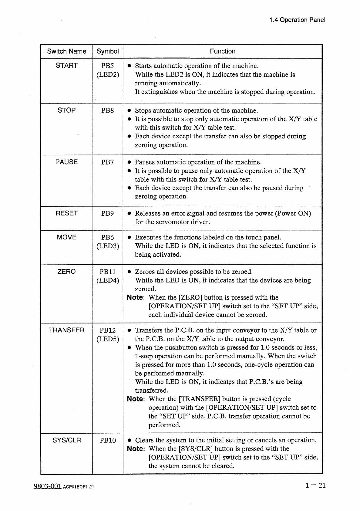
START
•
Starts
automatic
operation
of
the
machine
.
While
the
LED
2
is
ON
,
it
indicates
that
the
machine
is
running
automatically
.
It
extinguishes
when
the
machine
is
stopped
during
operation
.
PB
5
(
LED
2
)
STOP
PB
8
•
Stops
automatic
operation
of
the
machine
.
•
It
is
possible
to
stop
only
automatic
operation
of
the
X
/
Y
table
with
this
switch
for
X
/
Y
table
test
.
•
Each
device
except
the
transfer
can
also
be
stopped
during
zeroing
operation
.
PAUSE
•
Pauses
automatic
operation
of
the
machine
.
•
It
is
possible
to
pause
only
automatic
operation
of
the
X
/
Y
table
with
this
switch
for
X
/
Y
table
test
.
•
Each
device
except
the
transfer
can
also
be
paused
during
zeroing
operation
.
PB
7
RESET
•
Releases
an
error
signal
and
resumes
the
power
(
Power
ON
)
for
the
servomotor
driver
.
PB
9
MOVE
•
Executes
the
functions
labeled
on
the
touch
panel
.
While
the
LED
is
ON
,
it
indicates
that
the
selected
function
is
being
activated
.
PB
6
(
LED
3
)
ZERO
•
Zeroes
all
devices
possible
to
be
zeroed
.
While
the
LED
is
ON
,
it
indicates
that
the
devices
are
being
zeroed
.
Note
:
When
the
[
ZERO
]
button
is
pressed
with
the
[
OPERATION
/
SET
UP
]
switch
set
to
the
“
SET
UP
”
side
,
each
individual
device
cannot
be
zeroed
.
PB
11
(
LED
4
)
TRANSFER
•
Transfers
the
P
.
C
.
B
.
on
the
input
conveyor
to
the
X
/
Y
table
or
the
P
.
C
.
B
.
on
the
X
/
Y
table
to
the
output
conveyor
.
•
When
the
pushbutton
switch
is
pressed
for
1.0
seconds
or
less
,
1
-
step
operation
can
be
performed
manually
.
When
the
switch
is
pressed
for
more
than
1.0
seconds
,
one
-
cycle
operation
can
be
performed
manually
.
While
the
LED
is
ON
,
it
indicates
that
P
.
C
.
B
.
?
s
are
being
transferred
.
Note
:
When
the
[
TRANSFER
]
button
is
pressed
(
cycle
operation
)
with
the
[
OPERATION
/
SET
UP
]
switch
set
to
the
“
SET
UP
”
side
,
P
.
C
.
B
.
transfer
operation
cannot
be
performed
.
PB
12
(
LED
5
)
•
Clears
the
system
to
the
initial
setting
or
cancels
an
operation
.
Note
:
When
the
[
SYS
/
CLR
]
button
is
pressed
with
the
[
OPERATION
/
SET
UP
]
switch
set
to
the
“
SET
UP
”
side
,
the
system
cannot
be
cleared
.
SYS
/
CLR
PB
10
1
-
21
9803
-
001
ACP
01
EOP
1
-
21