1OPERATION_.pdf - 第61页
1.4 Operation Panel Symbol Function Switch Name • Starts automatic operation of the machine . While the LED 2 is ON , it indicates that the machine is running automatically . It extinguishes when the machine is stopped d…
1.4
Operation
Panel
1
,
4
,
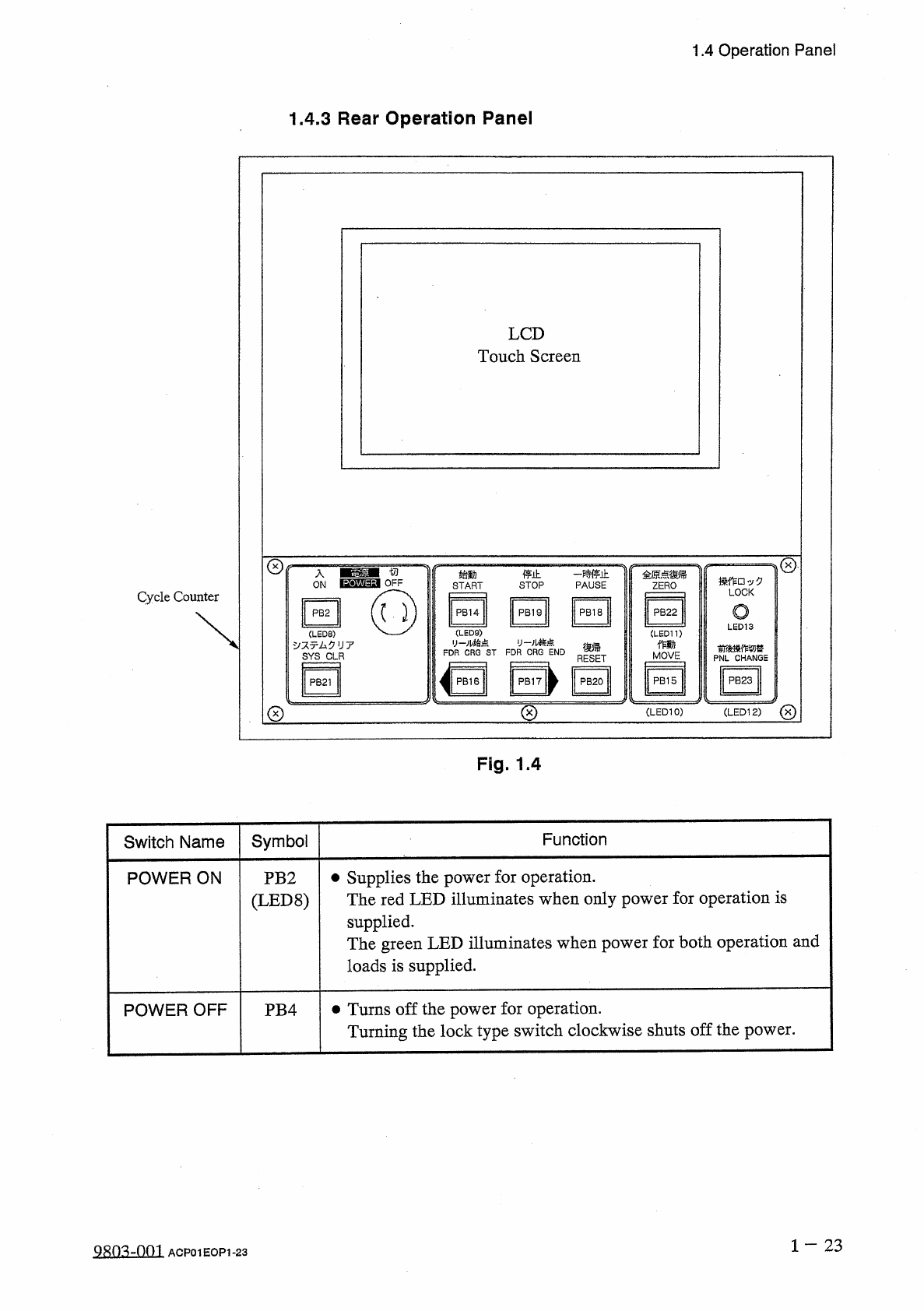
3
Rear
Operation
Panel
LCD
Touch
Screen
©
切
入
停止
-
m
±
PAUSE
始動
全原点鶴
ZERO
操作
□
,
:
/
夕
LOCK
OFF
ON
STOP
START
Cycle
Counter
o
PB
14
PB
2
PB
19
PB
18
PB
22
LED
13
(
LED
9
)
y
-
儿始点
y
-
祕点
;
CRG
ST
FDR
CRG
END
(
LED
8
)
、
:
/
又亍厶夕
U
7
SYS
CLR
(
LED
11
)
作動
役帰
PNL
CHANGE
FDR
MOVE
RESET
^
PB
16
PB
17
卜
PB
23
PB
15
PB
21
PB
20
©
©
(
LED
10
)
(
LED
12
)
Fig
.
1.4
Function
Symbol
Switch
Name
•
Supplies
the
power
for
operation
.
The
red
LED
illuminates
when
only
power
for
operation
is
supplied
.
The
green
LED
illuminates
when
power
for
both
operation
and
loads
is
supplied
.
POWER
ON
PB
2
(
LED
8
)
•
Turns
off
the
power
for
operation
.
Turning
the
lock
type
switch
clockwise
shuts
off
the
power
.
POWER
OFF
PB
4
1
一
23
Q
只
m
-
om
ACP
01
EOP
1
-
23
1.4
Operation
Panel
Symbol
Function
Switch
Name
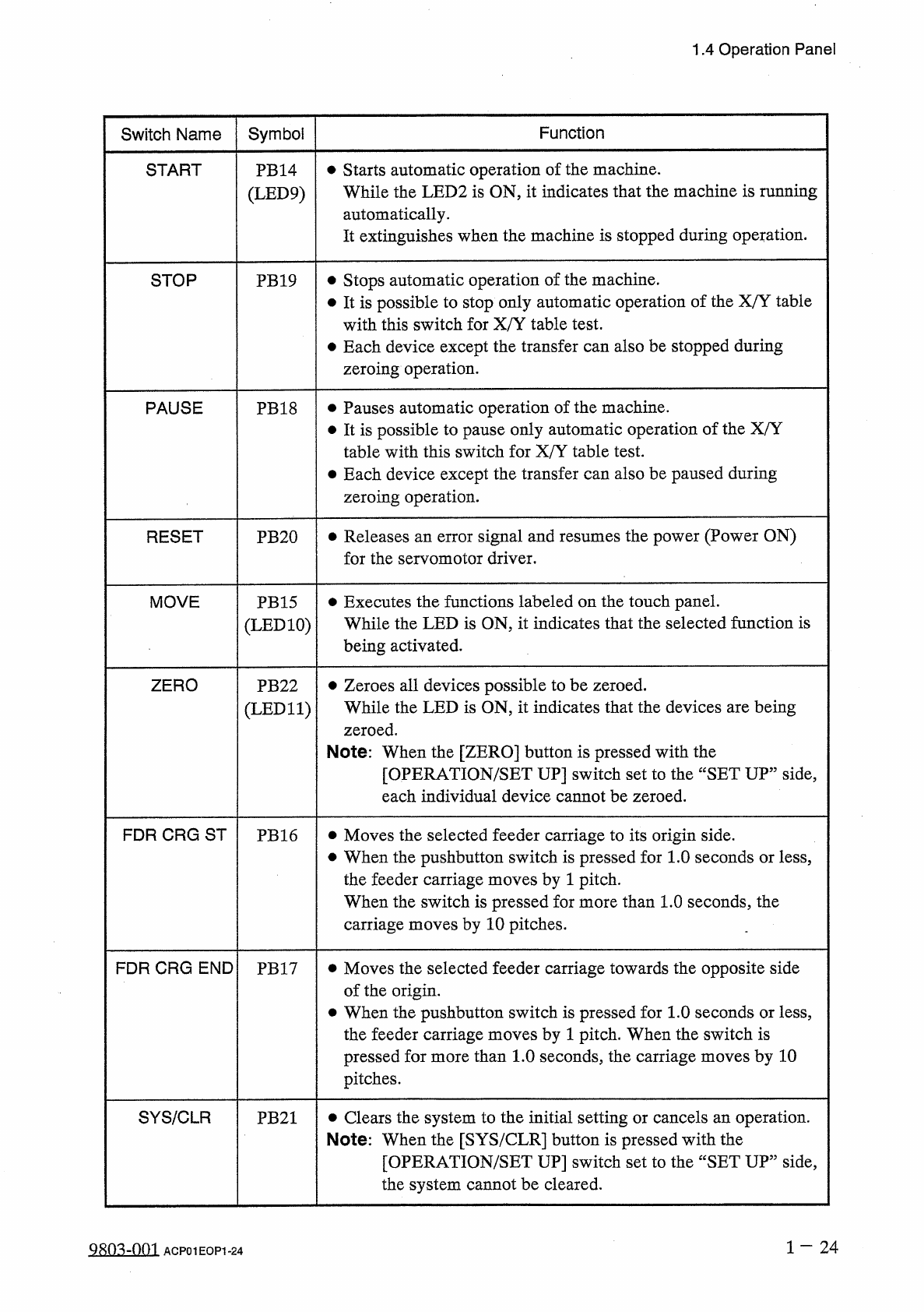
•
Starts
automatic
operation
of
the
machine
.
While
the
LED
2
is
ON
,
it
indicates
that
the
machine
is
running
automatically
.
It
extinguishes
when
the
machine
is
stopped
during
operation
.
START
PB
14
(
LED
9
)
Stops
automatic
operation
of
the
machine
.
•
It
is
possible
to
stop
only
automatic
operation
of
the
X
/
Y
table
with
this
switch
for
X
/
Y
table
test
.
•
Each
device
except
the
transfer
can
also
be
stopped
during
zeroing
operation
.
STOP
PB
19
•
Pauses
automatic
operation
of
the
machine
.
•
It
is
possible
to
pause
only
automatic
operation
of
the
X
/
Y
table
with
this
switch
for
X
/
Y
table
test
.
•
Each
device
except
the
transfer
can
also
be
paused
during
zeroing
operation
.
PAUSE
PB
18
•
Releases
an
error
signal
and
resumes
the
power
(
Power
ON
)
for
the
servomotor
driver
.
RESET
PB
20
•
Executes
the
functions
labeled
on
the
touch
panel
.
While
the
LED
is
ON
,
it
indicates
that
the
selected
function
is
being
activated
.
MOVE
PB
15
(
LED
10
)
•
Zeroes
all
devices
possible
to
be
zeroed
.
While
the
LED
is
ON
,
it
indicates
that
the
devices
are
being
zeroed
.
Note
:
When
the
[
ZERO
]
button
is
pressed
with
the
[
OPERATION
/
SET
UP
]
switch
set
to
the
“
SET
UP
”
side
,
each
individual
device
cannot
be
zeroed
.
ZERO
PB
22
(
LED
11
)
FDR
CRG
ST
•
Moves
the
selected
feeder
carriage
to
its
origin
side
.
•
When
the
pushbutton
switch
is
pressed
for
1.0
seconds
or
less
,
the
feeder
carriage
moves
by
1
pitch
.
When
the
switch
is
pressed
for
more
than
1.0
seconds
,
the
carriage
moves
by
10
pitches
.
PB
16
FDR
CRG
END
•
Moves
the
selected
feeder
carriage
towards
the
opposite
side
of
the
origin
.
•
When
the
pushbutton
switch
is
pressed
for
1.0
seconds
or
less
,
the
feeder
carriage
moves
by
1
pitch
.
When
the
switch
is
pressed
for
more
than
1.0
seconds
,
the
carriage
moves
by
10
pitches
.
PB
17
SYS
/
CLR
•
Clears
the
system
to
the
initial
setting
or
cancels
an
operation
.
Note
:
When
the
[
SYS
/
CLR
]
button
is
pressed
with
the
[
OPERATION
/
SET
UP
]
switch
set
to
the
“
SET
UP
”
side
,
the
system
cannot
be
cleared
.
PB
21
9803
-
001
ACP
01
EOP
1
-
24
1.4
Operation
Panel
Switch
Name
Symbol
Function
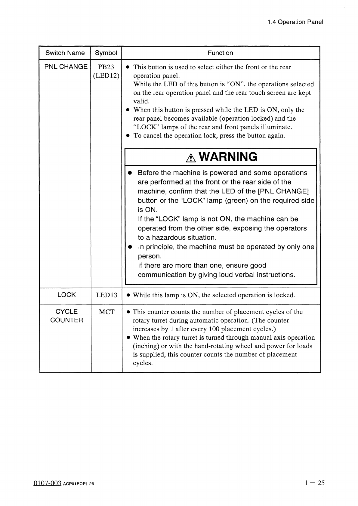
PNLCHANGE
•
This
button
is
used
to
select
either
the
front
or
the
rear
operation
panel
.
While
the
LED
of
this
button
is
‘
‘
ON
’’
,
the
operations
selected
on
the
rear
operation
panel
and
the
rear
touch
screen
are
kept
valid
.
•
When
this
button
is
pressed
while
the
LED
is
ON
,
only
the
rear
panel
becomes
available
(
operation
locked
)
and
the
“
LOCK
”
lamps
of
the
rear
and
front
panels
illuminate
.
•
To
cancel
the
operation
lock
,
press
the
button
again
.
PB
23
(
LED
12
)
A
WARNING
•
Before
the
machine
is
powered
and
some
operations
are
performed
at
the
front
or
the
rear
side
of
the
machine
,
confirm
that
the
LED
of
the
[
PNL
CHANGE
]
button
or
the
“
LOCK
”
lamp
(
green
)
on
the
required
side
is
ON
.
If
the
“
LOCK
”
lamp
is
not
ON
,
the
machine
can
be
operated
from
the
other
side
,
exposing
the
operators
to
a
hazardous
situation
.
•
In
principle
,
the
machine
must
be
operated
by
only
one
person
.
If
there
are
more
than
one
,
ensure
good
communication
by
giving
loud
verbal
instructions
.
LOCK
•
While
this
lamp
is
ON
,
the
selected
operation
is
locked
.
LED
13
CYCLE
COUNTER
•
This
counter
counts
the
number
of
placement
cycles
of
the
rotary
turret
during
automatic
operation
.
(
The
counter
increases
by
1
after
every
100
placement
cycles
.
)
•
When
the
rotary
turret
is
turned
through
manual
axis
operation
(
inching
)
or
with
the
hand
-
rotating
wheel
and
power
for
loads
is
supplied
,
this
counter
counts
the
number
of
placement
cycles
.
MCT
1
-
25
0107
-
003
ACP
01
EOP
1
-
25