1OPERATION_.pdf - 第68页
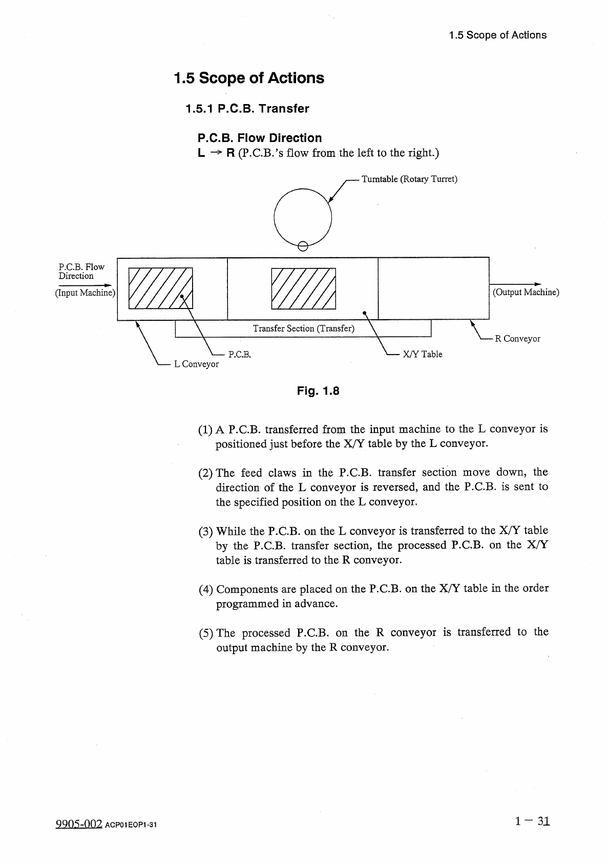
1.5 Scope of Actions 1.5 Scope of Actions 1.5 . 1 P . C . B . Transfer P . C . B . Flow Direction L — R ( P . C . B . ’ s flow from the left to the right . ) Turntable ( Rotary Turret ) P . C . B . Flow Direction ( Input…
1.4
Operation
Panel
1.4
.
6
[
C
1
READY
]
and
[
C
2
READY
]
Buttons
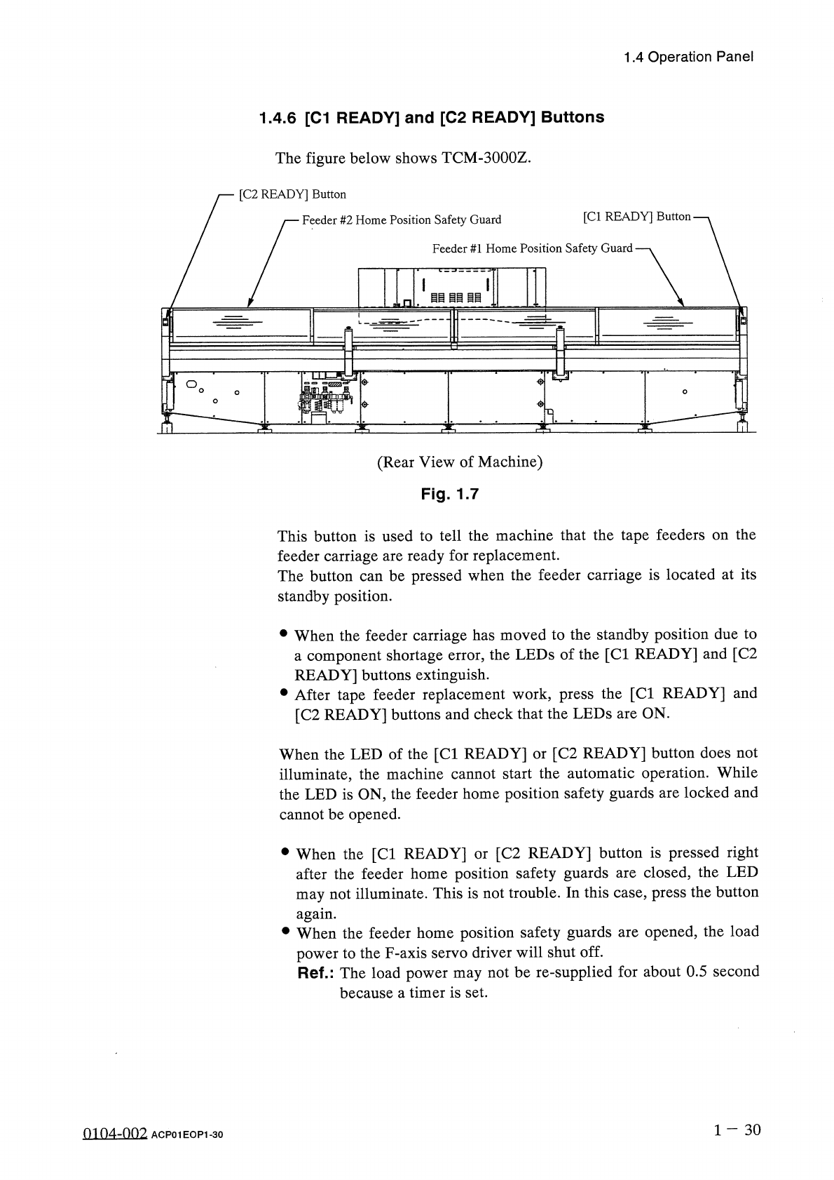
The
figure
below
shows
TCM
-
3000
Z
.
[
C
2
READY
]
Button
A
(
Rear
View
of
Machine
)
Fig
.
1.7
This
button
is
used
to
tell
the
machine
that
the
tape
feeders
on
the
feeder
carriage
are
ready
for
replacement
.
The
button
can
be
pressed
when
the
feeder
carriage
is
located
at
its
standby
position
.
•
When
the
feeder
carriage
has
moved
to
the
standby
position
due
to
a
component
shortage
error
,
the
LEDs
of
the
[
Cl
READY
]
and
[
C
2
READY
]
buttons
extinguish
.
•
After
tape
feeder
replacement
work
,
press
the
[
Cl
READY
]
and
[
C
2
READY
]
buttons
and
check
that
the
LEDs
are
ON
.
When
the
LED
of
the
[
Cl
READY
]
or
[
C
2
READY
]
button
does
not
illuminate
,
the
machine
cannot
start
the
automatic
operation
.
While
the
LED
is
ON
,
the
feeder
home
position
safety
guards
are
locked
and
cannot
be
opened
.
•
When
the
[
Cl
READY
]
or
[
C
2
READY
]
button
is
pressed
right
after
the
feeder
home
position
safety
guards
are
closed
,
the
LED
may
not
illuminate
.
This
is
not
trouble
.
In
this
case
,
press
the
button
again
.
•
When
the
feeder
home
position
safety
guards
are
opened
,
the
load
power
to
the
F
-
axis
servo
driver
will
shut
off
.
Ref
.
:
The
load
power
may
not
be
re
-
supplied
for
about
0.5
second
because
a
timer
is
set
.
1
-
30
0104
-
002
ACP
01
EOP
1
-
30
1.5
Scope
of
Actions
1.5
Scope
of
Actions
1.5
.
1
P
.
C
.
B
.
Transfer
P
.
C
.
B
.
Flow
Direction
L
—
R
(
P
.
C
.
B
.
’
s
flow
from
the
left
to
the
right
.
)
Turntable
(
Rotary
Turret
)
P
.
C
.
B
.
Flow
Direction
(
Input
Machine
)
(
Output
Machine
)
V
Transfer
Section
(
Transfer
)
R
Conveyor
P
.
C
.
B
.
X
/
Y
Table
L
Conveyor
Fig
.
1.8
(
1
)
A
P
.
C
.
B
.
transferred
from
the
input
machine
to
the
L
conveyor
is
positioned
just
before
the
X
/
Y
table
by
the
L
conveyor
.
down
,
the
direction
of
the
L
conveyor
is
reversed
,
and
the
P
.
C
.
B
.
is
sent
to
the
specified
position
on
the
L
conveyor
.
(
2
)
The
feed
claws
in
the
P
.
C
.
B
.
transfer
section
move
(
3
)
While
the
P
.
C
.
B
.
on
the
L
conveyor
is
transferred
to
the
X
/
Y
table
by
the
P
.
C
.
B
.
transfer
section
,
the
processed
P
.
C
.
B
.
on
the
X
/
Y
table
is
transferred
to
the
R
conveyor
.
(
4
)
Components
are
placed
on
the
P
.
C
.
B
.
on
the
X
/
Y
table
in
the
order
programmed
in
advance
.
the
R
conveyor
is
transferred
to
the
(
5
)
The
processed
P
.
C
.
B
.
output
machine
by
the
R
conveyor
.
on
1
-
31
QQ
05
-
nf
)
2
ACP
01
EOP
1
-
31
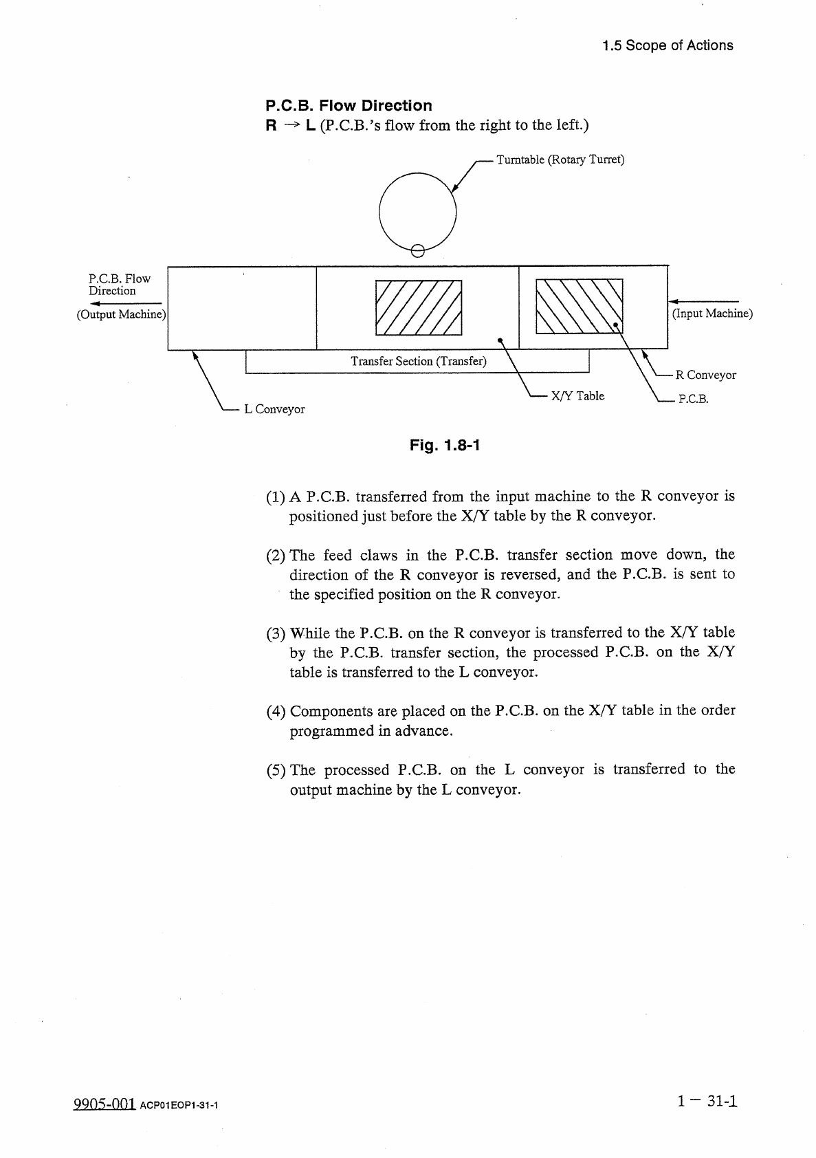
1.5
Scope
of
Actions
P
.
C
.
B
.
Flow
Direction
R
—
L
(
P
.
C
.
B
.
’
s
flow
from
the
right
to
the
left
.
)
Turntable
(
Rotary
Turret
)
P
.
C
.
B
.
Flow
Direction
(
Output
Machine
)
(
Input
Machine
)
Transfer
Section
(
Transfer
)
R
Conveyor
X
/
Y
Table
P
.
C
.
B
.
L
Conveyor
Fig
.
1.8
-
1
(
1
)
A
P
.
C
.
B
.
transferred
from
the
input
machine
to
the
R
conveyor
is
positioned
just
before
the
X
/
Y
table
by
the
R
conveyor
.
(
2
)
The
feed
claws
in
the
P
.
C
.
B
.
transfer
section
move
down
,
the
direction
of
the
R
conveyor
is
reversed
,
and
the
P
.
C
.
B
.
is
sent
to
the
specified
position
on
the
R
conveyor
.
(
3
)
While
the
P
.
C
.
B
.
on
the
R
conveyor
is
transferred
to
the
X
/
Y
table
by
the
P
.
C
.
B
.
transfer
section
,
the
processed
P
.
C
.
B
.
on
the
X
/
Y
table
is
transferred
to
the
L
conveyor
.
(
4
)
Components
are
placed
on
the
P
.
C
.
B
.
on
the
X
/
Y
table
in
the
order
programmed
in
advance
.
(
5
)
The
processed
P
.
C
.
B
.
on
the
L
conveyor
is
transferred
to
the
output
machine
by
the
L
conveyor
.
1
—
31
-
1
QQns
-
om
ACP
01
EOP
1
-
31
-
1