1OPERATION_.pdf - 第70页
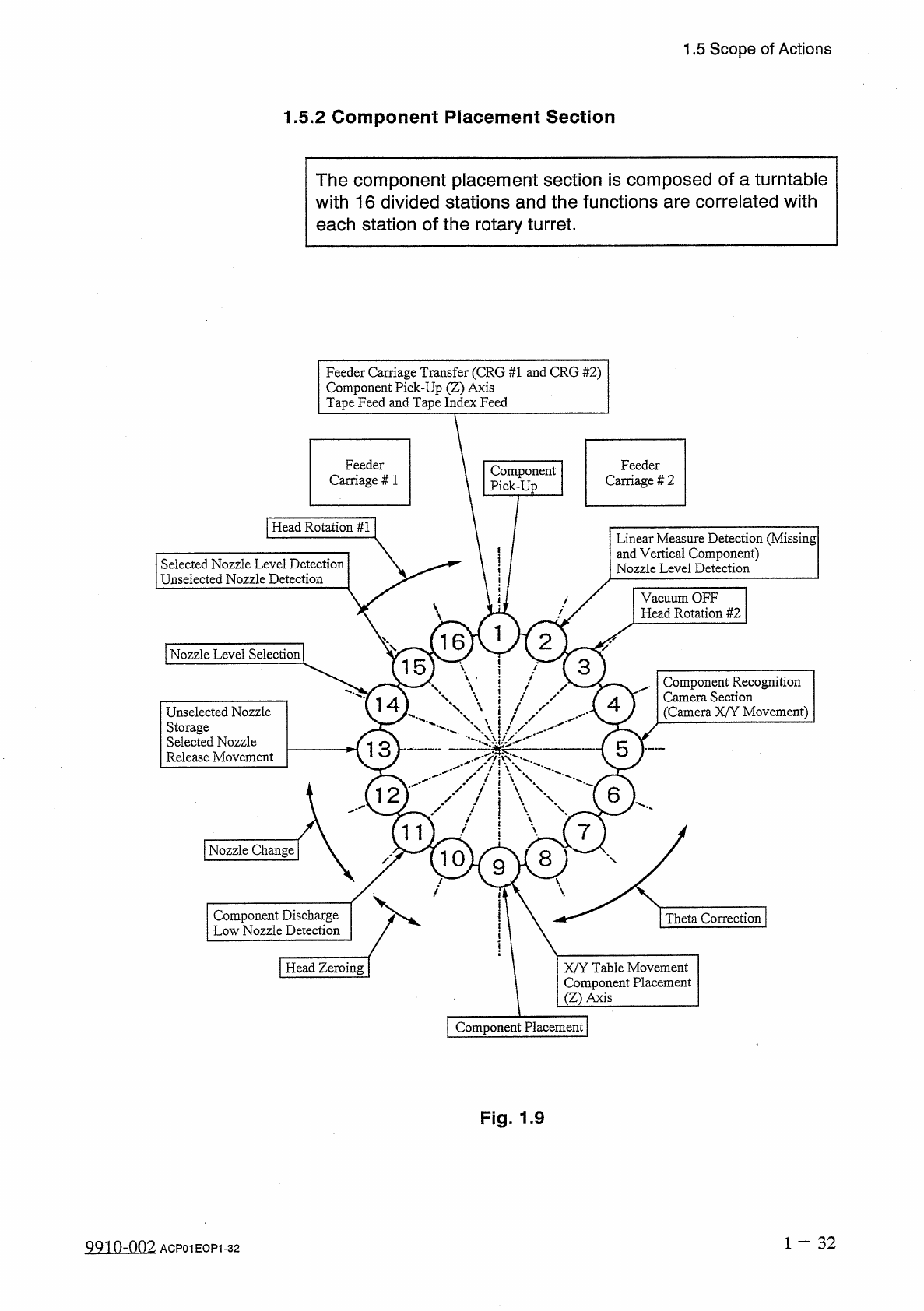
1.5 Scope of Actions 1.5 . 2 Component Placement Section The component placement section is composed of a turntable with 16 divided stations and the functions are correlated with each station of the rotary turret . Feede…
1.5
Scope
of
Actions
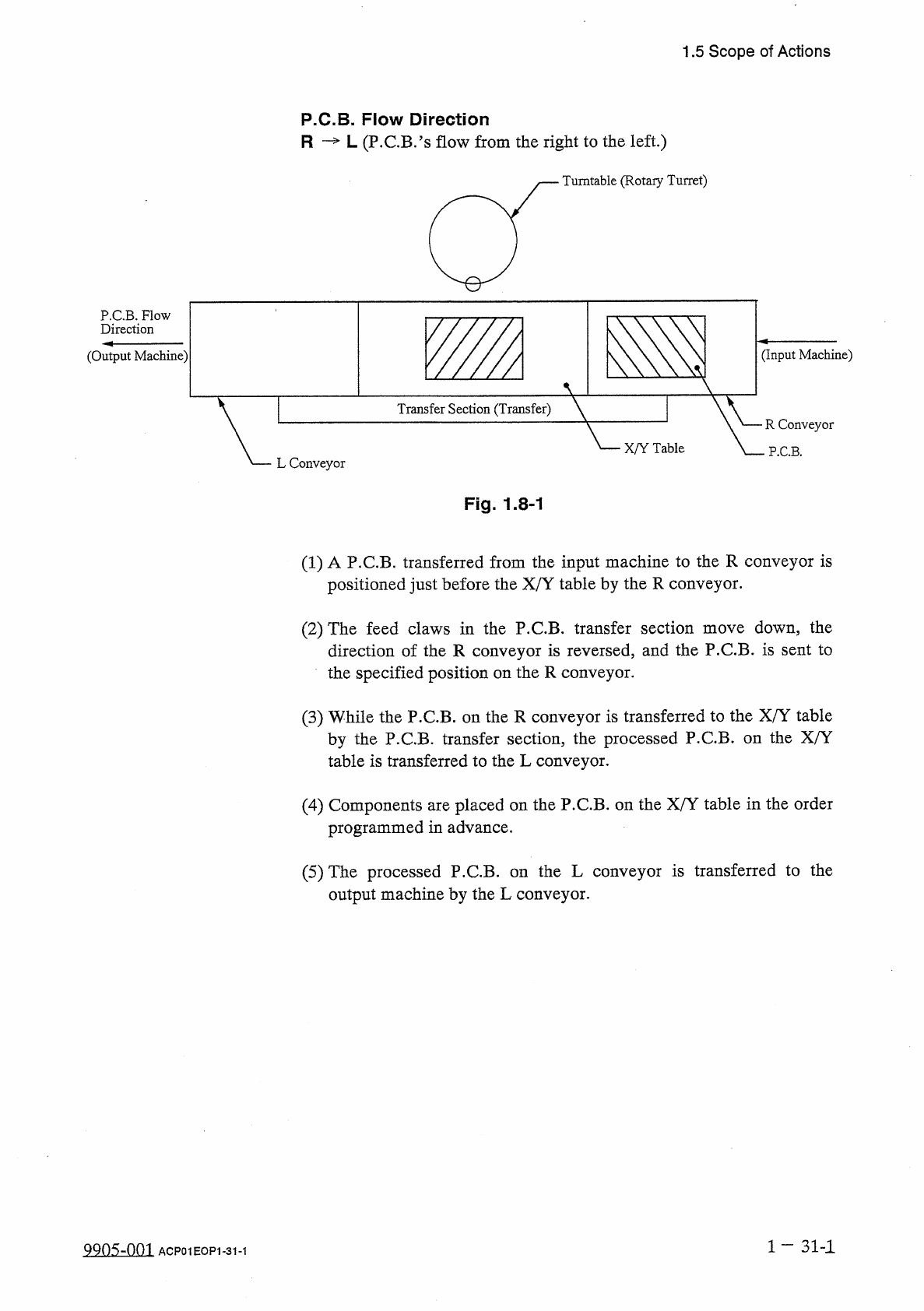
P
.
C
.
B
.
Flow
Direction
R
—
L
(
P
.
C
.
B
.
’
s
flow
from
the
right
to
the
left
.
)
Turntable
(
Rotary
Turret
)
P
.
C
.
B
.
Flow
Direction
(
Output
Machine
)
(
Input
Machine
)
Transfer
Section
(
Transfer
)
R
Conveyor
X
/
Y
Table
P
.
C
.
B
.
L
Conveyor
Fig
.
1.8
-
1
(
1
)
A
P
.
C
.
B
.
transferred
from
the
input
machine
to
the
R
conveyor
is
positioned
just
before
the
X
/
Y
table
by
the
R
conveyor
.
(
2
)
The
feed
claws
in
the
P
.
C
.
B
.
transfer
section
move
down
,
the
direction
of
the
R
conveyor
is
reversed
,
and
the
P
.
C
.
B
.
is
sent
to
the
specified
position
on
the
R
conveyor
.
(
3
)
While
the
P
.
C
.
B
.
on
the
R
conveyor
is
transferred
to
the
X
/
Y
table
by
the
P
.
C
.
B
.
transfer
section
,
the
processed
P
.
C
.
B
.
on
the
X
/
Y
table
is
transferred
to
the
L
conveyor
.
(
4
)
Components
are
placed
on
the
P
.
C
.
B
.
on
the
X
/
Y
table
in
the
order
programmed
in
advance
.
(
5
)
The
processed
P
.
C
.
B
.
on
the
L
conveyor
is
transferred
to
the
output
machine
by
the
L
conveyor
.
1
—
31
-
1
QQns
-
om
ACP
01
EOP
1
-
31
-
1
1.5
Scope
of
Actions
1.5
.
2
Component
Placement
Section
The
component
placement
section
is
composed
of
a
turntable
with
16
divided
stations
and
the
functions
are
correlated
with
each
station
of
the
rotary
turret
.
Feeder
Carriage
Transfer
(
CRG
#
1
and
CRG
#
2
)
Component
Pick
-
Up
(
Z
)
Axis
Tape
Feed
and
Tape
Index
Feed
Feeder
Carriage
#
1
Feeder
Carriage
#
2
Component
Pick
-
Up
|
Head
Rotation
#
1
Linear
Measure
Detection
(
Missing
and
Vertical
Component
)
Nozzle
Level
Detection
Selected
Nozzle
Level
Detection
Unselected
Nozzle
Detection
Vacuum
OFF
Head
Rotation
#
2
2
16
[
NozzleLevel
Selection
|
3
15
)
\
Component
Recognition
Camera
Section
(
Camera
X
/
Y
Movement
)
\
14
4
Unselected
Nozzle
Storage
Selected
Nozzle
Release
Movement
"
、
'
皱
:
5
13
6
12
11
7
I
Nozzle
Change
W
9
8
|
Theta
Correction
|
Component
Discharge
Low
Nozzle
Detection
I
Head
Zeroing
X
/
Y
Table
Movement
Component
Placement
(
Z
)
Axis
|
Component
Placement
|
Fig
.
1.9
1
-
32
QQ
10
-
002
ACP
01
EOP
1
-
32
1.5
Scope
of
Actions
Station
#
1
:
Component
Pick
-
Up
Section
Feeder
Carriage
#
1
and
#
2
Transfer
,
Component
Pick
-
Up
(
Z
)
Axis
,
Tape
Feed
,
and
Tape
Index
Feed
①
Feeder
Carriage
#
1
Tape
feeders
set
on
a
feeder
carriage
are
carried
to
the
pick
-
up
position
according
to
the
pattern
program
data
.
②
Component
Pick
-
Up
(
Z
)
Axis
(
Vacuum
Nozzle
Height
)
The
height
of
a
vacuum
nozzle
is
changed
according
to
the
level
of
the
component
pick
-
up
surface
on
tape
feeder
.
③
Tape
Feed
and
Tape
Index
Feed
The
tape
index
feed
claw
moves
the
tape
forward
in
the
range
of
±
2
pitches
according
to
the
pattern
program
data
.
and
#
2
Transfer
Station
#
2
:
Linear
Measure
Detection
(
Missing
and
Vertical
Components
)
,
Nozzle
Level
Detection
•
Checking
is
done
whether
a
component
is
picked
up
by
the
selected
nozzle
or
not
.
•
Nozzle
level
(
height
)
can
also
be
taught
.
(
Teaching
Operation
)
Station
#
3
:
Vacuum
OFF
,
Head
Rotation
#
2
①
Vacuum
OFF
When
it
is
detected
that
no
component
is
picked
up
at
station
#
2
,
the
vacuum
valve
closes
.
②
Head
Rotation
#
2
The
head
6
section
is
rotated
and
the
vacuum
nozzle
is
moved
to
the
position
where
components
can
be
recognized
.
Station
#
4
:
No
Function
Station
#
5
:
Component
Recognition
Camera
Section
(
Camera
X
/
Y
Movement
)
Components
are
recognized
.
Note
:
For
both
back
and
front
recognition
The
camera
X
/
Y
is
moved
at
nozzle
teaching
and
stationed
at
its
origin
when
a
component
is
recognized
.
Stations
#
6
,
#
7
,
and
#
8
:
Theta
Correction
“
Component
Placement
Angle
+
Rotational
Direction
”
is
corrected
.
(
Max
.
+
360
°
)
1
—
33
QQ
10
-
002
ACP
01
EOP
1
-
33