1OPERATION_.pdf - 第83页
1.10 [ PNL CHANGE ] Buttons • When one of the [ PNL CHANGE ] buttons is pressed , the LED illuminates , indicating that the button is selected . At the same time , both green LED 7 and LED 13 ( LEDs of “ LOCK ” ) also il…
1.10
[
PNL
CHANGE
]
Buttons
1.10
[
PNL
CHANGE
]
Buttons
The
machine
is
equipped
with
operation
panels
.
Each
operation
panel
(
front
and
provided
with
the
[
PNL
CHANGE
]
button
.
Either
one
of
the
two
buttons
can
be
set
available
in
operation
.
It
is
impossible
to
activate
both
buttons
at
the
same
time
.
When
the
button
is
active
,
the
LED
illuminates
.
When
the
[
OPERATION
]
switch
is
set
to
“
SET
UP
’
’
,
the
front
panel
is
locked
forcibly
.
pairs
of
touch
screens
and
panels
)
two
rear
are
(
1
)
Listed
below
are
valid
buttons
when
the
[
PNL
CHANGE
]
button
is
pressed
.
•
Touch
Screen
Switch
•
[
START
]
Button
•
[
RESET
]
Button
•
[
ZERO
]
Button
•
[
MOVE
]
Button
•
[
TRANSFER
]
Button
•
[
FDR
CRG
ST
]
Button
•
[
FDR
CRG
END
]
Button
•
[
SYS
CLR
]
Button
Note
:
The
[
STOP
]
and
[
PAUSE
]
buttons
can
be
activated
anytime
regardless
of
the
[
PNL
CHANGE
]
buttons
.
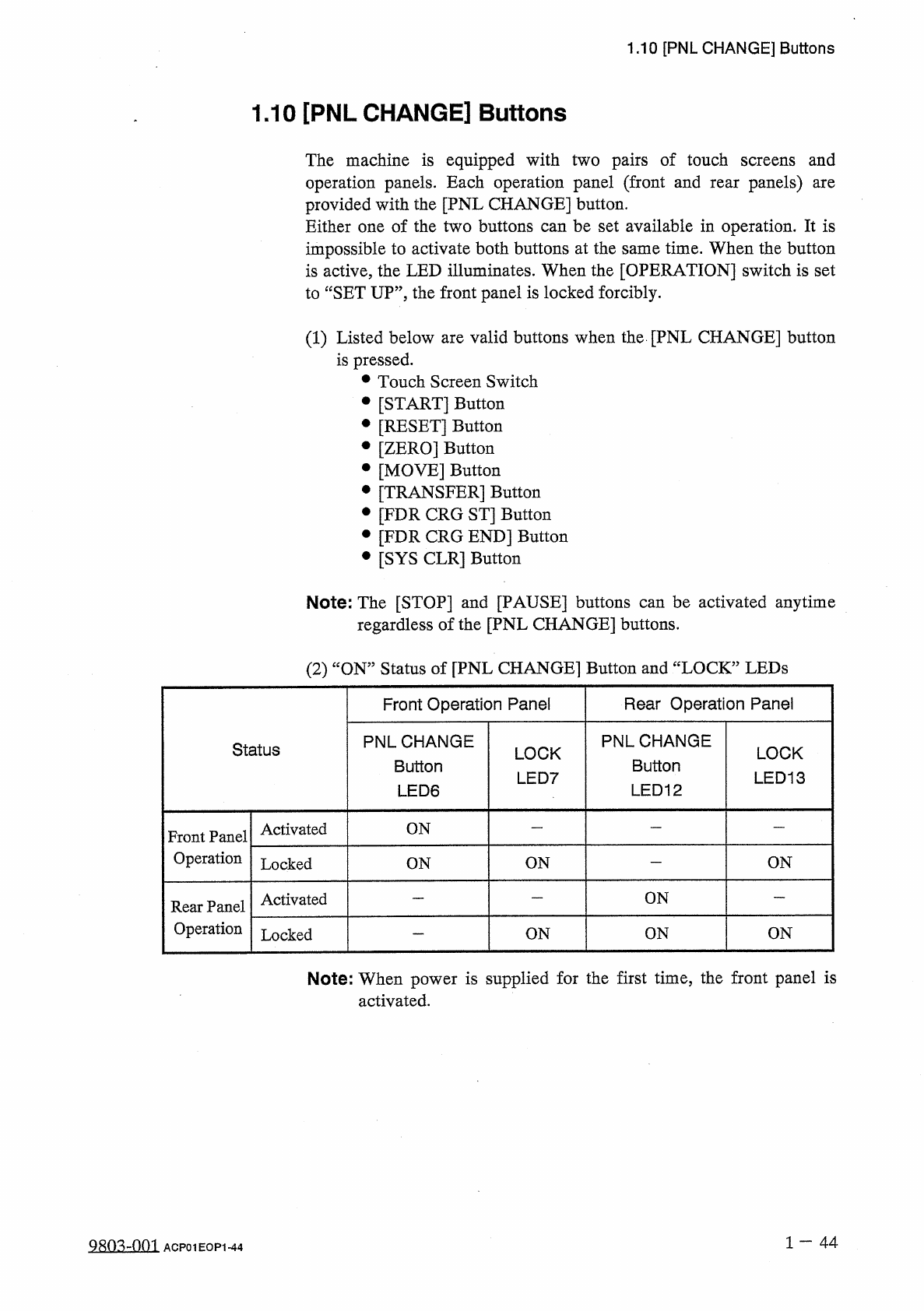
(
2
)
“
ON
”
Status
of
[
PNL
CHANGE
]
Button
and
“
LOCK
”
LEDs
Rear
Operation
Panel
Front
Operation
Panel
PNLCHANGE
Button
LED
12
PNLCHANGE
Button
LED
6
Status
LOCK
LED
13
LOCK
LED
7
Activated
ON
Front
Panel
Operation
ON
ON
Locked
ON
ON
Activated
Rear
Panel
Operation
ON
ON
ON
Locked
Note
:
When
power
is
supplied
for
the
first
time
,
the
front
panel
is
activated
.
1
一
44
ACP
01
EOP
1
-
44
1.10
[
PNL
CHANGE
]
Buttons
•
When
one
of
the
[
PNL
CHANGE
]
buttons
is
pressed
,
the
LED
illuminates
,
indicating
that
the
button
is
selected
.
At
the
same
time
,
both
green
LED
7
and
LED
13
(
LEDs
of
“
LOCK
”
)
also
illuminate
because
they
CHANGE
]
button
and
the
“
LOCK
”
LED
on
the
panel
are
ON
,
the
operation
panel
becomes
activated
.
In
this
case
,
when
the
[
PNL
CHANGE
]
button
on
the
unselected
operation
panel
is
pressed
,
the
operation
panels
cannot
be
changed
from
one
to
the
other
as
long
as
the
“
LOCK
”
LED
is
ON
.
interconnected
.
When
the
LED
of
the
[
PNL
operation
are
same
•
To
cancel
“
LOCK
”
mode
on
the
selected
operation
panel
,
press
the
[
PNL
CHANGE
]
button
located
on
the
panel
again
.
The
“
LOCK
”
mode
is
canceled
and
both
green
LED
7
and
LED
13
extinguish
.
•
The
operation
panels
can
be
changed
from
one
to
the
other
by
the
desired
panel
only
pressing
the
[
PNL
CHANGE
]
button
when
both
are
not
in
“
LOCK
”
mode
.
Either
one
of
the
operation
panels
on
be
selected
regardless
of
the
operation
mode
(
Ex
.
:
RUN
”
or
“
PAUSE
”
mode
)
of
the
machine
.
can
When
the
console
panel
is
not
locked
and
the
[
STOP
]
or
[
PAUSE
]
button
on
the
unselected
console
panel
is
pressed
,
the
console
panel
on
the
pressed
button
side
becomes
activated
automatically
and
the
LED
of
the
[
CONSOLE
CHANGE
]
button
also
illuminates
automatically
.
•
When
the
[
SYS
CLR
]
button
on
the
operation
panel
in
“
LOCK
’
mode
is
pressed
,
the
“
LOCK
”
mode
is
canceled
.
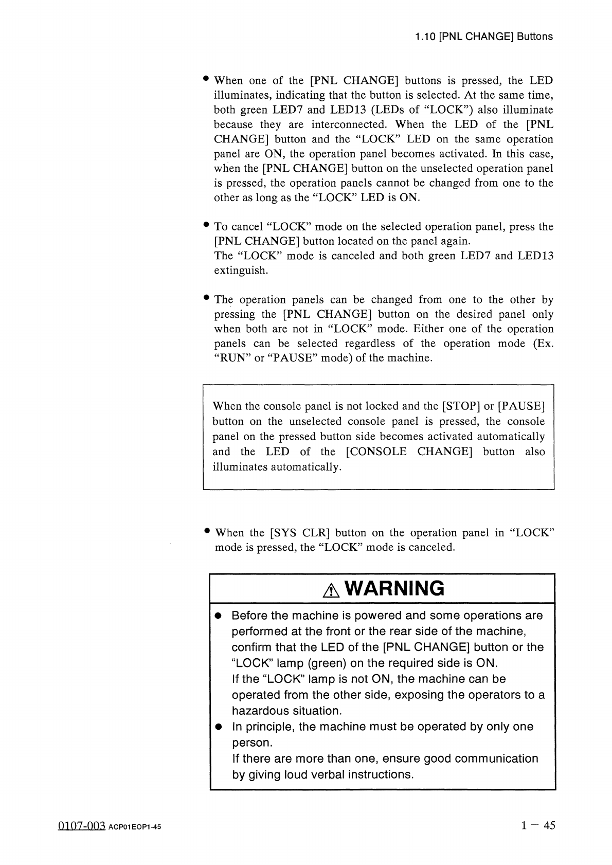
A
WARNING
•
Before
the
machine
is
powered
and
some
operations
are
performed
at
the
front
or
the
rear
side
of
the
machine
,
confirm
that
the
LED
of
the
[
PNL
CHANGE
]
button
or
the
“
LOCK
”
lamp
(
green
)
on
the
required
side
is
ON
.
If
the
“
LOCK
”
lamp
is
not
ON
,
the
machine
can
be
operated
from
the
other
side
,
exposing
the
operators
to
a
hazardous
situation
.
•
In
principle
,
the
machine
must
be
operated
by
only
one
person
.
If
there
are
more
than
one
,
ensure
good
communication
by
giving
loud
verbal
instructions
.
1
-
45
m
07
-
nn
^
ACP
01
EOP
1
-
45
1.11
[
OPERATION
]
Switch
1.11
[
OPERATION
]
Switch
When
the
[
OPERATION
/
SET
UP
]
switch
is
set
to
the
“
SET
UP
”
side
,
the
safety
check
switch
on
the
front
safety
door
is
deactivated
and
setup
operations
become
possible
with
the
front
safety
door
being
open
.
雕奄与无人
/
(
力
&
<
;
:
—
眘使无丰
r
FOR
AUTHORIZED
PERSONNEL
'
S
USE
ONLY
Selection
Key
(
for
the
[
OPERATION
/
SET
UP
]
Switch
)
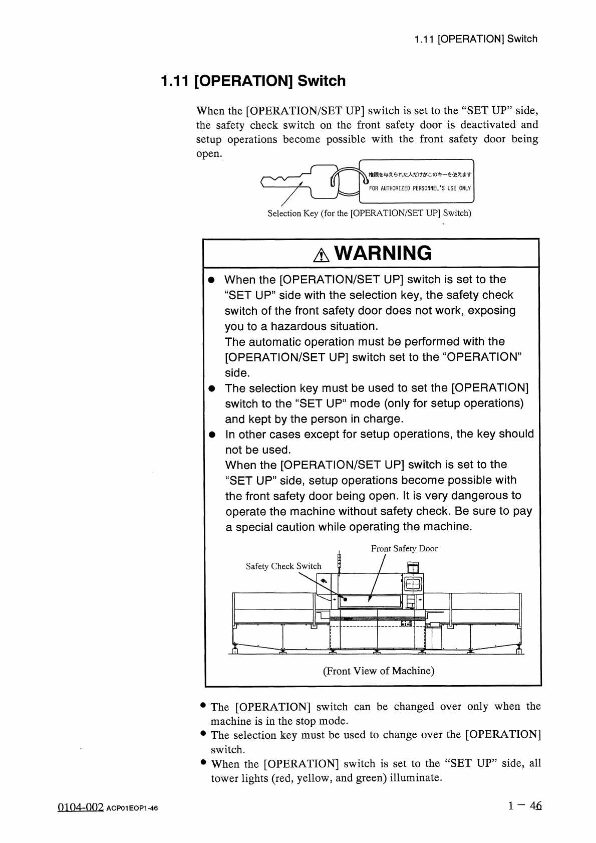
A
WARNING
•
When
the
[
OPERATION
/
SET
UP
]
switch
is
set
to
the
“
SET
UP
”
side
with
the
selection
key
,
the
safety
check
switch
of
the
front
safety
door
does
not
work
,
exposing
you
to
a
hazardous
situation
.
The
automatic
operation
must
be
performed
with
the
[
OPERATION
/
SET
UP
]
switch
set
to
the
“
OPERATION
”
side
.
•
The
selection
key
must
be
used
to
set
the
[
OPERATION
]
switch
to
the
“
SET
UP
”
mode
(
only
for
setup
operations
)
and
kept
by
the
person
in
charge
.
參
In
other
cases
except
for
setup
operations
,
the
key
should
not
be
used
.
When
the
[
OPERATION
/
SET
UP
]
switch
is
set
to
the
“
SET
UP
”
side
,
setup
operations
become
possible
with
the
front
safety
door
being
open
.
It
is
very
dangerous
to
operate
the
machine
without
safety
check
.
Be
sure
to
pay
a
special
caution
while
operating
the
machine
.
Front
Safety
Door
!
m
Safety
Check
Switch
TZ
(
Front
View
of
Machine
)
be
changed
only
when
the
•
The
[
OPERATION
]
switch
machine
is
in
the
stop
mode
.
•
The
selection
key
must
be
used
to
change
over
the
[
OPERATION
]
over
can
switch
.
•
When
the
[
OPERATION
]
switch
is
set
to
the
“
SET
UP
”
side
,
all
tower
lights
(
red
,
yellow
,
and
green
)
illuminate
.
1
一
46
0104
-
002
ACP
01
EOP
1
-
46