00193854-0402_AI_LBO_HS60-D4_DE+EN.pdf - 第28页
2 Assembly Instructions "Long Board Option" SIPLACE HS-60 / D4 HS-60 / D4 "Long Board Option" 05/2007 Edition 28 2.2 Part s required 2.2.1 T ools and consumables required – Set of hexagon socket sp an…
HS-60 / D4 "Long Board Option" 2 Assembly Instructions "Long Board Option" SIPLACE HS-60 / D4
05/2007 Edition
27
2 Assembly Instructions "Long Board
Option" SIPLACE HS-60 / D4
An additional "stopper base unit, complete" (part no.: 00368385-01) must be ordered for the dual
conveyor. 2
2
2.1 Restrictions
– Pass-through height for components on the underside of the PCB = 25 mm
– Minimum PCB width approx. 110 mm (50 mm if the "stopper base unit, complete" is dismantled
and the travel limiting screws are removed).
2 Assembly Instructions "Long Board Option" SIPLACE HS-60 / D4 HS-60 / D4 "Long Board Option"
05/2007 Edition
28
2.2 Parts required
2.2.1 Tools and consumables required
– Set of hexagon socket spanners
– Cable stripper
– Crimping tool (AMP)
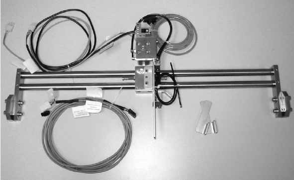
2.2.2 Content of assembly kit
-
Complete mechanism (for single conveyor) Part no. 00119427-02 1x
- Complete mechanism (for dual conveyor) Part no. 00368385-01 1x
- Option CD for enabling the function
on the line computer Part. no. 00355462-01 1x
- Assembly instructions Part. no. 00193854-xx 1x
2.2.3 Spare parts
- Kabel Zylinderschalter Opt. St. lange LP Item no.: 00369638-01
- Magnetventil MZH-5/2-M3-L-LED Item no.: 00332940-01
- Lichttaster mit Kabel Stopper lange LP Item no.: 00369637-01
- Anschlusskabel Option lange Leiterplatte Item no.: 00369636-01
2
2

HS-60 / D4 "Long Board Option" 2 Assembly Instructions "Long Board Option" SIPLACE HS-60 / D4
05/2007 Edition
29
2.3 Safety instructions
DANGER
The PCB length modification assembly must only be carried out by SIPLACE service engi-
neers.
The safety instructions from the “Operational safety” chapter of the user manual and the service
manual take precedence over these instructions.
The SIPLACE HS-60 placement machine is supplied with main power voltage.
Consequently parts of these systems inside the machine frame carry dangerous voltages, even
when switched off at the main switch.
BEFORE starting any work, shut down the operating system correctly, then switch the machine
OFF at the main switch and disconnect from the main power supply. Then switch off the compres-
sed air supply at the main valve on the compressed air unit in the machine frame, and vent by
actuating the needle valve in the compressed air unit. (This is particularly important since the air
that remains in the pneumatic cutting device after uncoupling / dismantling the component chan-
geover table is a potential source of injury).
Always follow the accident prevention regulations, DIN or other standards and special safety rules
applicable in your country. Always follow DIN EN 60204 when working inside the machine frame.
On the HS-60, there is DANGER for heart pacemaker wearers in the vicinity of the linear motors,
as described in detail in the "Special safety instructions for working in the vicinity of strong magne-
tic fields" section of the user manual and service manual.
Pay attention to the information concerning residual voltages in the Operational Safety chapter.
Remember to follow the ESD regulations (see Operational safety chapter).
During the assembly, always secure the machine to prevent access by other people and to pre-
vent it being switched on again. The procedure is described in the “Locking the machine…” sec-
tion of the user manual.
Working with the SITEST program further increases the risk of accident.
The SITEST program must only be used by authorized personnel.
The component table must always be retracted and correctly coupled before any work with the
SITEST program starts. 2
2.3.1 Definitions
2
Note 2
2
2
2