00193854-0402_AI_LBO_HS60-D4_DE+EN.pdf - 第33页
HS-60 / D4 "Lo ng Board Option" 2 Assembly Instructions "Long Board Option" SIPLACE HS-60 / D4 05/2007 Edition 33 : Loosely fasten the fixing p lates 2 to the fixing plates 1 that you have already ass…
2 Assembly Instructions "Long Board Option" SIPLACE HS-60 / D4 HS-60 / D4 "Long Board Option"
05/2007 Edition
32
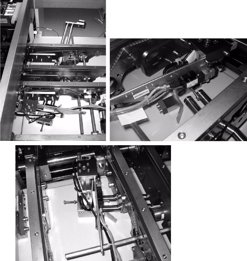
: Introduce the two guide shafts beneath the conveyor side walls into the pre-assembled stopper
base unit assembly (00368385-01).
2
2
: Guide these guide shafts into the two fixing plates 1 (00368312-01) and fix them to the two at-
tachments in the output belt through the existing holes.
: Fit the fixing plates 2 (00368313-01) on both ends of the guide shafts.
: Fix the guide shafts on one side using grubscrews M4x6-DIN914 in fixing plate 2.
2
2
HS-60 / D4 "Long Board Option" 2 Assembly Instructions "Long Board Option" SIPLACE HS-60 / D4
05/2007 Edition
33
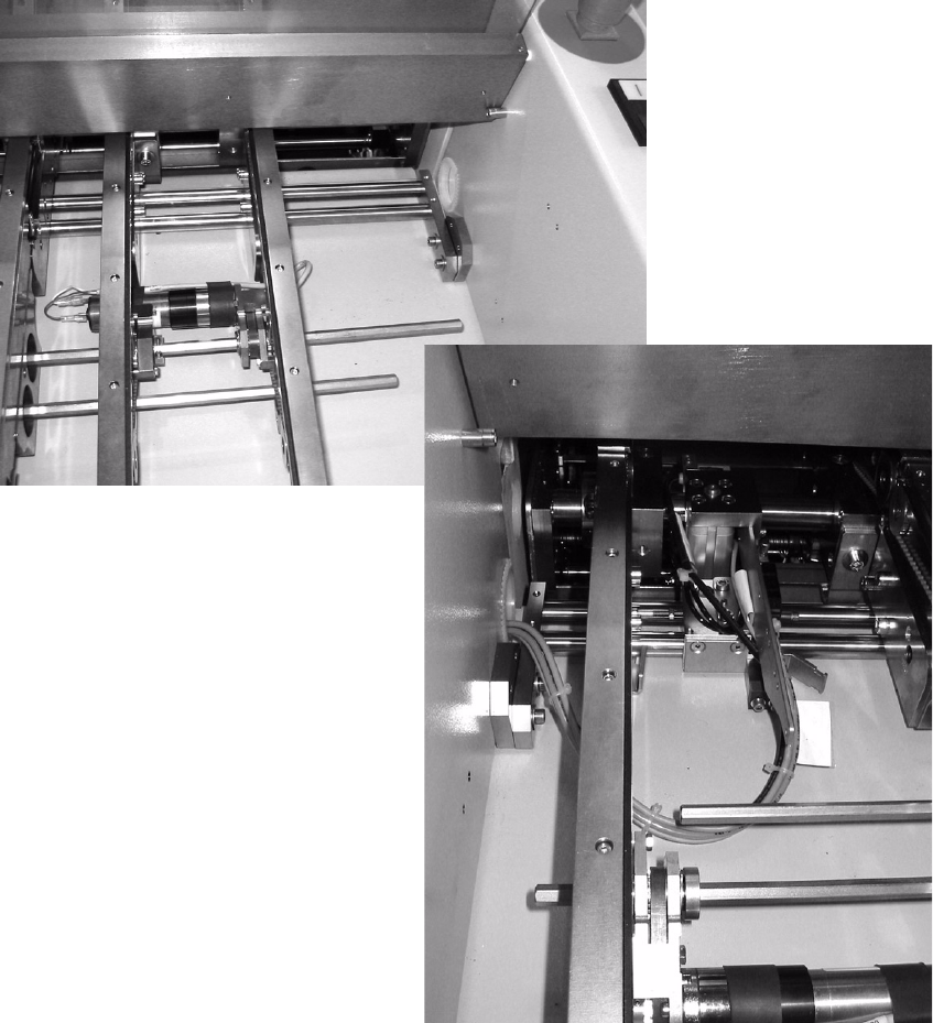
: Loosely fasten the fixing plates 2 to the fixing plates 1 that you have already assembled (using
screws M5x20-DIN 912 and washers 5.3-DIN 9021).
2
2
2
2
2
2
2
2 Assembly Instructions "Long Board Option" SIPLACE HS-60 / D4 HS-60 / D4 "Long Board Option"
05/2007 Edition
34
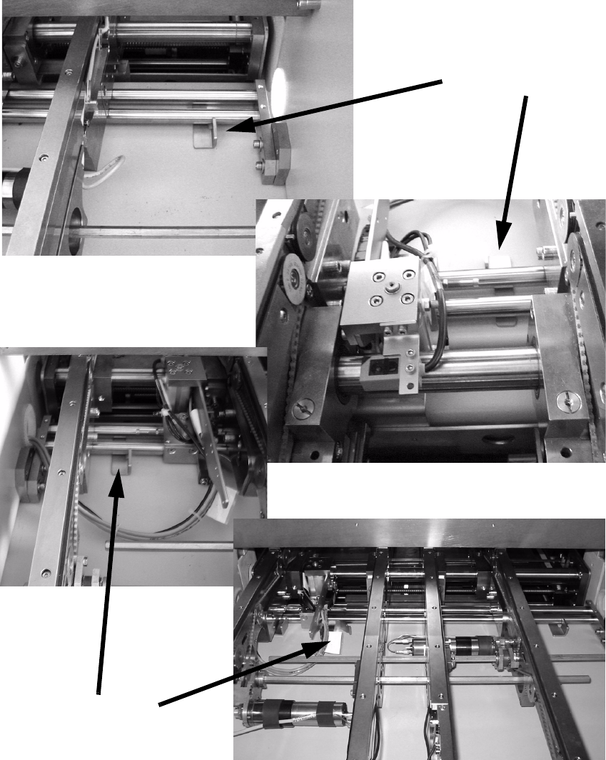
: Adjust the position in the vertical and horizontal directions using an adjusting gauge
(00373397-01).
Set the horizontal distance between the side wall flanges on the two side parts and the guide
shaft to 27 mm.
2
2
Adjusting gauge
Adjusting gauge