00195779-0102_UM_D4_SR605_EN.pdf - 第109页
User manual SIPLACE D4 3 Technical data for the machine From software version SR.605.xx 07/2008 EN Edition 3.7 PCB conveyor system 109 PCBs on conveyor tracks 1 and 2 are moved synchr onously onto the conveyor se ctions …
3 Technical data for the machine User manual SIPLACE D4
3.7 PCB conveyor system From software version SR.605.xx 07/2008 EN Edition
108
throughout the placement operation. The placement sequence starts as soon as a PCB has
moved onto the processing belt. The PCBs are processed one after another.
If the placement sequence is interrupted, the conveyor interface will be disabled and the PCBs
currently on the processing belts will be completed.
The conveyor interface is disabled or enabled simultaneously for both transport tracks.
3
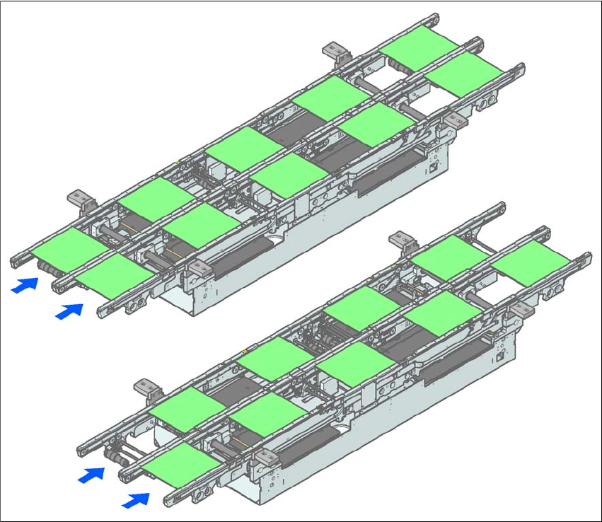
Fig. 3.7 - 4 Transport modes
3.7.3.7 Synchronous transport mode
Description 3
In synchronous mode, two PCBs of the same size are moved into the placement position at the
same time. They must be processed as a common panel.
In this way, the top and bottom of a PCB can be processed on a single line, and the time required
to transport the PCB is shorter since two PCBs are always transported at the same time. It also
ensures better utilization of the nozzle configuration.
Synchronous transport mode
Asynchronous transport mode
User manual SIPLACE D4 3 Technical data for the machine
From software version SR.605.xx 07/2008 EN Edition 3.7 PCB conveyor system
109
PCBs on conveyor tracks 1 and 2 are moved synchronously onto the conveyor sections (i.e. the
conveyors are controlled synchronously, but independently of one another). The components to
be placed on conveyor tracks 1 and 2 must be organized into a panel via two subpanels. (See the
SIPLACE Pro user manual).
If only one conveyor track (or center conveyor) is full when the placement sequence starts, the
subpanel on this section will be identified as “not for placement”.
Restrictions 3
If the dual conveyor is operated in synchronous mode, the ‘PCB whispering down the line’ option
is deactivated. PCB barcode operation is not supported in this mode. The "Global bad fiducial"
option cannot be used.
3.7.4 Controlling and width adjustment
3.7.4.1 Controlling the PCB conveyor system using the single functions menu
The online help contains information on controlling the PCB conveyor system and on the single
functions menu.
3.7.4.2 Automatic width adjustment
When the command is received, the conveyors are set to the desired width one after another. Dif-
ferent widths are possible.
3
See the online help for detailed information about changing the conveyor track width.
3 Technical data for the machine User manual SIPLACE D4
3.7 PCB conveyor system From software version SR.605.xx 07/2008 EN Edition
110
3.7.5 Technical data
3.7.5.1 Technical data for the PCB single conveyor
3
3
Fixed conveyor edge Right or left
PCB format
Standard (length x width)
Wide board option
Long board option
Long board option and
Wide board option
50 x 50 mm² to 368 x 460 mm²
a
50 x 50 mm² to 368 x 508 mm²
a
50 x 110 mm² to 610 x 460 mm²
a
50 x 110 mm² to 610 x 508 mm²
a
PCB thickness
Standard 0.3 mm to 4.5 mm ± 0.2 mm
(thicker PCBs available on request)
PCB warpage see Section 3.7.7
, page 113
PCB weight max. 3 kg
Clearance on PCB underside
Standard
Option
25 mm ± 0.2 mm
max. 40 mm ± 0.2 mm
Component-free PCB handling edge 3 mm
PCB changeover time 2.5 s
PCB positioning accuracy ± 0.5 mm
PCB conveyor height 830mm ± 15mm (standard)
900mm ± 15mm (optional)
930mm ± 15mm (optional)
950mm ± 15mm (SMEMA: optional)
Type of interface Siemens / SMEMA
b
Bad fiducial detection possible
Automatic width adjustment possible
a) With PCB widths > 450 mm make sure that the peripheral modules are also able to process these widths.
b) Option