00195779-0102_UM_D4_SR605_EN.pdf - 第14页
1 Introduction User manual SIPLACE D4 1.1 Machine description From software version SR.605.xx 07/2008 EN Edition 14 1.1 Machine description 1.1.1 SIPLACE D4 placement machine The high-speed placement mach ine SIPLACE D4 …
User manual SIPLACE D4 1 Introduction
From software version SR.605.xx 07/2008 EN Edition
13
1 Introduction
These operating instructions provide a manual or reference work for operating and setting up the
SIPLACE
®
D4 placement machine.
The header of each chapter contains the release and software version, to which this manual ap-
plies.
1
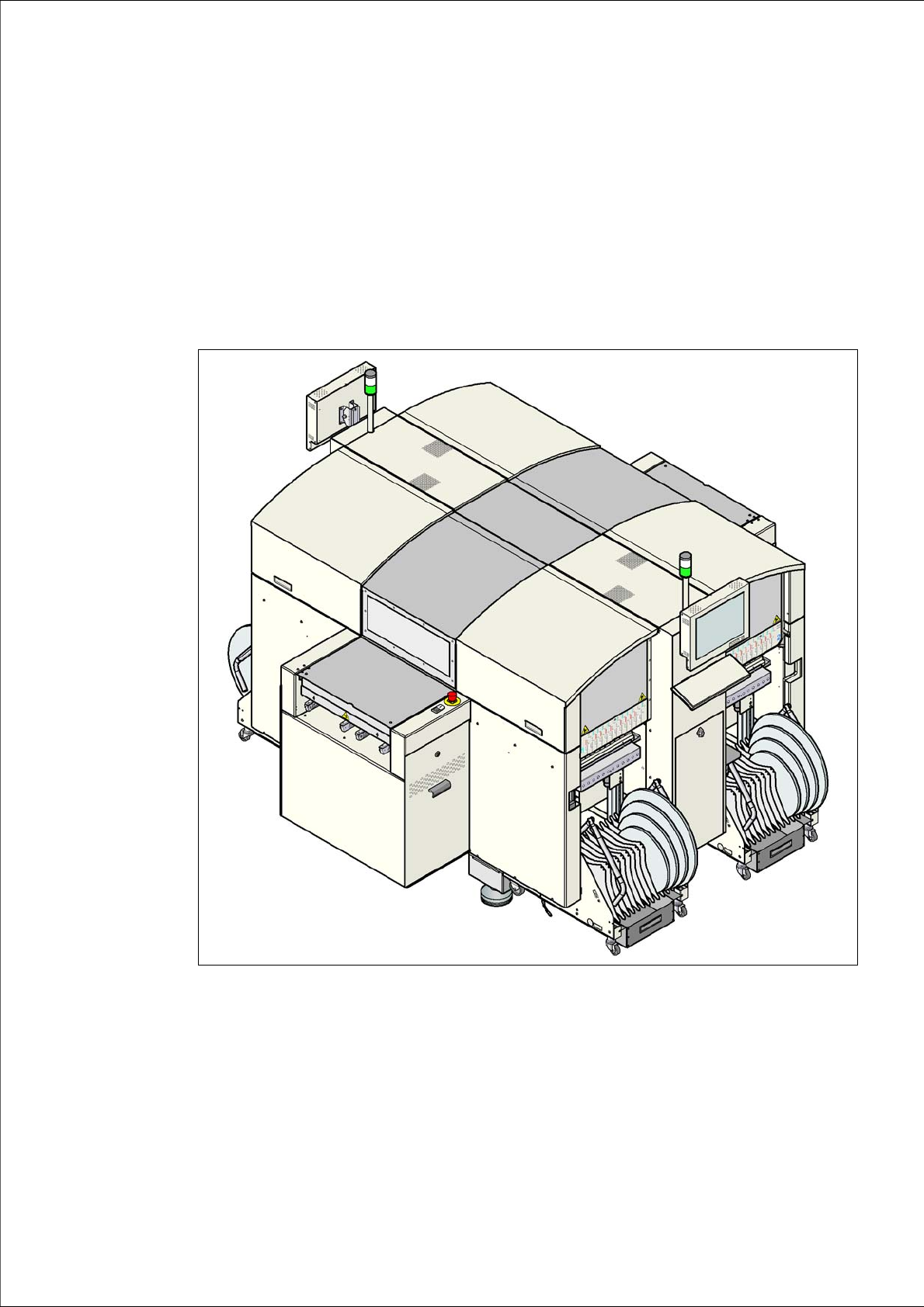
Fig. 1.0 - 1 SIPLACE D4 placement machine
1 Introduction User manual SIPLACE D4
1.1 Machine description From software version SR.605.xx 07/2008 EN Edition
14
1.1 Machine description
1.1.1 SIPLACE D4 placement machine
The high-speed placement machine SIPLACE D4 connects high placement rate with accuracy
and flexibility. The Collect&Place method is used as a placement procedure.
The SIPLACE D4 placement machine is equipped with four gantries which can be positioned
quickly and accurately in the X and Y directions.
There is a 12-segment Collect&Place head on each gantry. The gantries are combined in pairs to
form a common placement area.
Placement area 1: Gantries 1 and 4
Placement area 2: Gantries 2 and 3 1
The SIPLACE D4 placement machine is prepared to place 01005 components as standard. For
placement of 01005 components you simply need the optional 01005 package for the 12-segment
Collect&Place head. The component range ranges from 01005 components up to a size of 18.7
x 18.7 mm².
Digital vision modules perform the optical centering of the components. To do this there are digital
cameras available each with a different resolution.
A five-piece PCB conveyor, consisting of input belt, processing belt 1, intermediate belt, process-
ing belt 2 and output belt, carries the PCB into the processing position. As a further variant, it is
also possible to choose between the single conveyor or flexible dual conveyor with fixed side on
right or left. The PCBs are optically centered with the digital PCB camera.
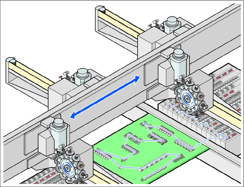
1.1.2 The SIPLACE principle
The moving head picks up the components from their stationary feeder, and places them on the
PCB, which is also stationary. This proven SIPLACE principle has many advantages:
– Short down times for refilling or splicing
– Even the smallest components (e.g. 01005) are picked up reliably
– The components cannot slip on the PCB
– Minimal traversing paths
High flexibility, cost-effectiveness and set-up reliability combine to ensure that the SIPLACE D4
placement system provides high productivity. Minimum down times increase utilization and thus
help to increase productivity.
User manual SIPLACE D4 1 Introduction
From software version SR.605.xx 07/2008 EN Edition 1.1 Machine description
15
1
Fig. 1.1 - 1 The SIPLACE principle
1.1.3 New options and performance features
The following options are available to extend the machines' functionality:
– 01005 package
The SIPLACE D4 placement machines are prepared to place 01005 components as stan-
dard. For placement simply retrofitting of the 12 segment Collect&Place head with the 01005
package is necessary. 1
– 3 x 8 mm 01005 tape feeder module
The tape feeder module specially developed for 01005 components makes components
available of the sizes 01005 to 0402. 1
– 3 x 8 mm SL tape feeder module
SL means shutterless, that is without a component cover. Dispensing with unnecessary me-
chanical parts reduces the procurement and maintenance costs for this feeder module. 1