00195779-0102_UM_D4_SR605_EN.pdf - 第147页
User manual SIPLACE D4 4 Setting up and commissioning From software version SR.605.xx 07/2008 EN Edition 4.1 Transport and delivery configuration 147 4 Setting up and commissioning 4.1 T ransport and delivery configurati…
3 Technical data for the machine User manual SIPLACE D4
3.10 Component trolley From software version SR.605.xx 07/2008 EN Edition
146
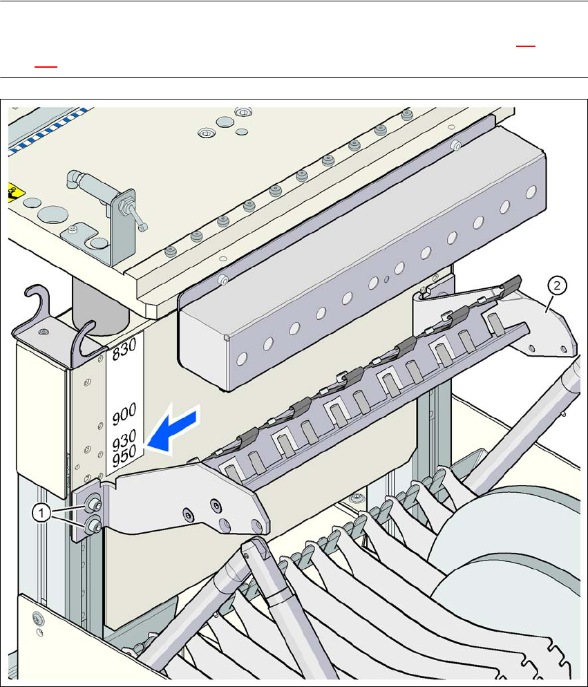
3.10.7.5 Adapter plate assembly position for 950 mm PCB conveyor height
PLEASE NOTE
The procedure for setting the height of the component trolley is described in Section 4.4
, from
page 180.
3
Fig. 3.10 - 11 Adapter plate assembly position for 950 mm PCB conveyor height
(1) Adapter plate
(2) Hexagon socket head screw, M6x20 with washer, 4x
User manual SIPLACE D4 4 Setting up and commissioning
From software version SR.605.xx 07/2008 EN Edition 4.1 Transport and delivery configuration
147
4 Setting up and commissioning
4.1 Transport and delivery configuration
4.1.1 Shipping packaging
Within Europe, the machine and the CO trolleys are supplied on two pallets and wrapped in plastic
film. They will be dispatched overseas in two robust wooden crates.
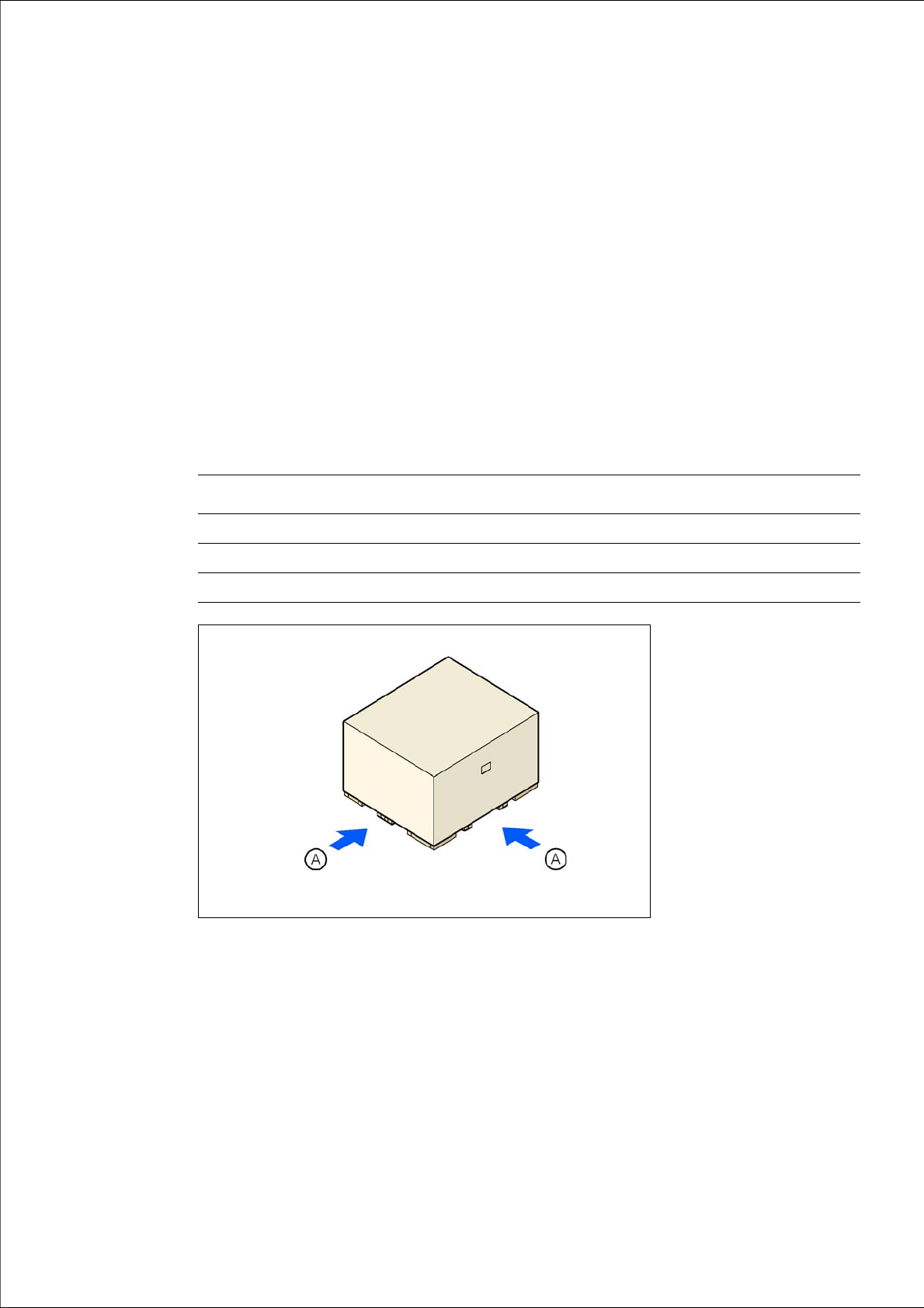
4.1.1.1 Dimensions of the shipping packaging
4
4
4
Fig. 4.1 - 1 Transport crate - dimension in millimeters
(A) Fork-lift attachment points
Crate for the machine Crate for the component trolleys
Length 2590 mm 1705 mm
Width 2410 mm 1200 mm
Height 1610 mm 1300 mm

4 Setting up and commissioning User manual SIPLACE D4
4.1 Transport and delivery configuration From software version SR.605.xx 07/2008 EN Edition
148
4.1.1.2 Weight of the machine prepared for dispatch
The following table contains the weights of the machines prepared for dispatch, including packag-
ing.
4
4.1.2 Configuration when delivered
The machine is configured as follows when delivered:
– The track on the single conveyor is set to a width of 210 mm. On the dual conveyor, the width
of conveyor track 1 is 100 mm and conveyor track 2 is 210 mm. These preset PCB conveyor
widths make it easier to remove the extension kits and conveyors on the input or output side
of the machine when this is necessary for reasons of space in order to transport the machine.
– Both keyboards (item 1 in Fig. 4.1 - 2
) are unplugged.
– The supporting plates for the keyboards (item 2 in Fig. 4.1 - 2
) are detached.
– Both monitors (item 3 in Fig. 4.1 - 2
) are dismantled.
– Both main fault indicators (item 4 in Fig. 4.1 - 2
) are dismantled.
– All the gantry axes are fixed with shipping braces.
Weight Dispatch within Europe Dispatch overseas
Machine 3326 kg 3594 kg
CO trolley 462 kg 556 kg