00195779-0102_UM_D4_SR605_EN.pdf - 第156页
4 Setting up and commissioning User manual SIPLACE D4 4.2 Infrastructure at the installation location From software version SR.605.xx 07/2008 EN Edition 156 4.2.4 Main power supply 4 Fig. 4.2 - 2 Position of the power su…
User manual SIPLACE D4 4 Setting up and commissioning
From software version SR.605.xx 07/2008 EN Edition 4.2 Infrastructure at the installation location
155
4.2.3.2 Compressed air connection on the machine
4
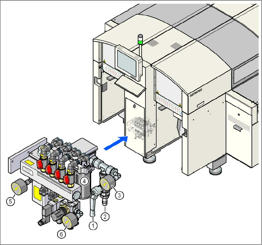
Fig. 4.2 - 1 Compressed air line connection
(1) Stop valve in the "OPEN" position
(2) Compressed air connection
(3) Manometer for the input pressure
Desired pressure: 0.55 - 1.0 MPa (5.5 - 10 bar), display range: 0 - 1.2 MPa (0 - 12 bar)
(4) Compressed air filter
(5) Manometer for the gantry distributor supply pressure
Desired pressure: 0.51 ± 0.01 MPa (5.1 ± 0.1 bar), display range: 0 - 1.2 MPa (0 - 12 bar)
(6) Manometer for the bulk case feeder modules supply pressure
Desired pressure: 0.25 ± 0.05 MPa (2.5 ± 0.5 bar), display range: 0 - 0.6 MPa (0 - 6 bar)
4 Setting up and commissioning User manual SIPLACE D4
4.2 Infrastructure at the installation location From software version SR.605.xx 07/2008 EN Edition
156
4.2.4 Main power supply
4
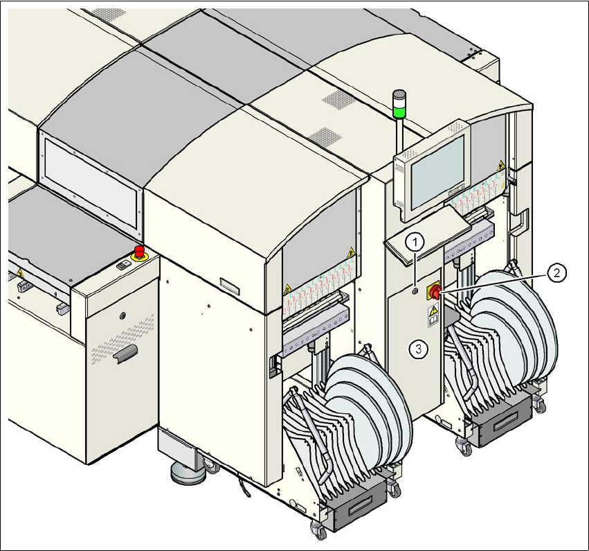
Fig. 4.2 - 2 Position of the power supply on the machine
4
(1) Lock
(2) Main power switch secured to prevent switching on again
(3) Cover
User manual SIPLACE D4 4 Setting up and commissioning
From software version SR.605.xx 07/2008 EN Edition 4.2 Infrastructure at the installation location
157
4.2.4.1 Danger notes
WARNING
The machine is supplied with 3 x 200 VAC, 3 x 208 VAC, 3 x 230 VAC, 3 x 380 VAC, 3 x 400 VAC
or 3x415VAC ± 5%, 50/60Hz main power voltage. This means that some parts of the system
carry potentially lethal voltages - even when switched off at the main power switch. Incorrect han-
dling of the machine can therefore result in death or severe injury or considerable damage to
equipment. 4
→ Always follow the applicable accident prevention and DIN regulations (particularly DIN EN 60
204, part 1).
→ Only trained and qualified personnel may remove the cover over the power supply unit and
connect the machine to the power supply.
4
4
4.2.4.2 Checking the main power supply
Check that the main power supply conforms to the prescribed machine specifications (see table
in Section 3.2
, page 88).
PLEASE NOTE: 4
The document entitled "Network configuration (electrical and compressed air) for SMD systems
on the customer's premises", item no. 00191409-xx, describes the action that can be taken to
meet the required specifications.
PLEASE NOTE: 4
For technical reasons, load peaks occur in the power supply. Please contact your power com-
pany to clarify the mains impedance, if necessary.
4
4
4.2.4.3 Power supply cable - specification
The following specifications apply to the power supply cable:
5 x 6 mm² for 3 x 380 VAC / 3 x 400 VAC / 3 x 415 VAC
5 x 6 mm² for 3 x 200 VAC / 3 x 208 VAC / 3 x 230 VAC
The color coding for the wires will depend on the country in which the system is operated.