00195779-0102_UM_D4_SR605_EN.pdf - 第162页
4 Setting up and commissioning User manual SIPLACE D4 4.2 Infrastructure at the installation location From software version SR.605.xx 07/2008 EN Edition 162 4.2.4.6 Checking the inrush current limit ation jumpers The inr…
User manual SIPLACE D4 4 Setting up and commissioning
From software version SR.605.xx 07/2008 EN Edition 4.2 Infrastructure at the installation location
161
PLEASE NOTE 4
The Japanese supply network (3 x 200 VAC) and supply networks in the USA (3 x 208 VAC) are
connected to terminals for 3 x 204 VAC.
4
4
4
4
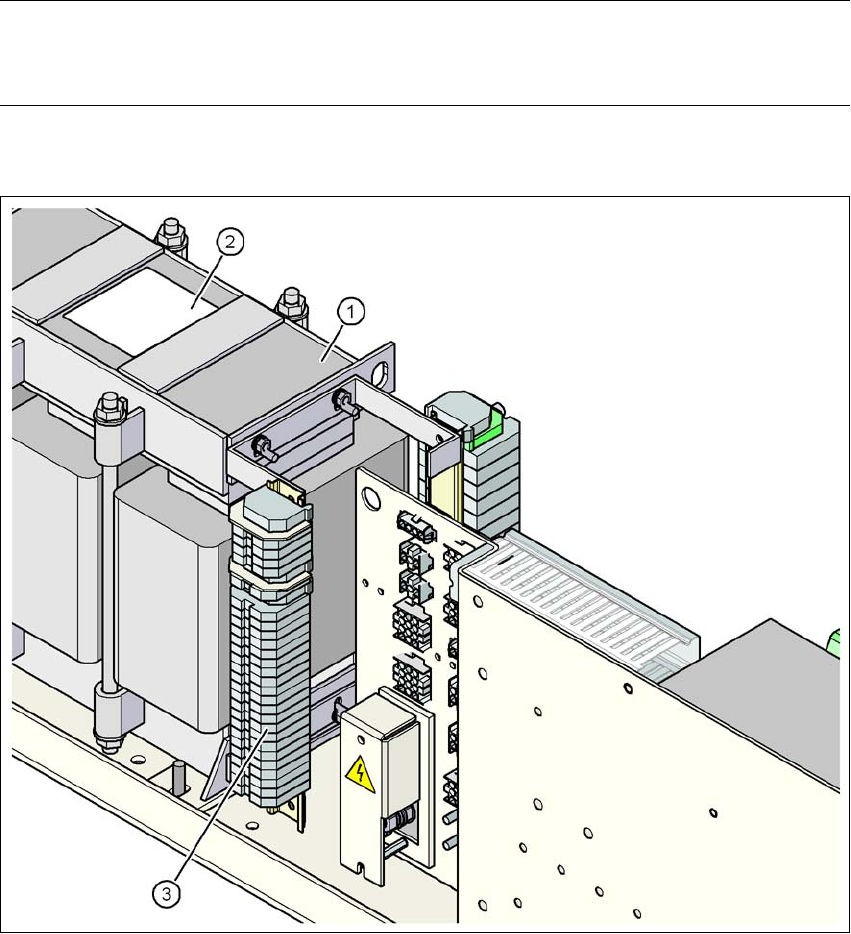
Fig. 4.2 - 6 Position of the terminal block with primary connections for the three-phase transformer T1
(1) Three-phase transformer T1
(2) Sign with the connection wiring diagram for the primary side
(3) Terminal block with primary connections for the three-phase transformer T1
4 Setting up and commissioning User manual SIPLACE D4
4.2 Infrastructure at the installation location From software version SR.605.xx 07/2008 EN Edition
162
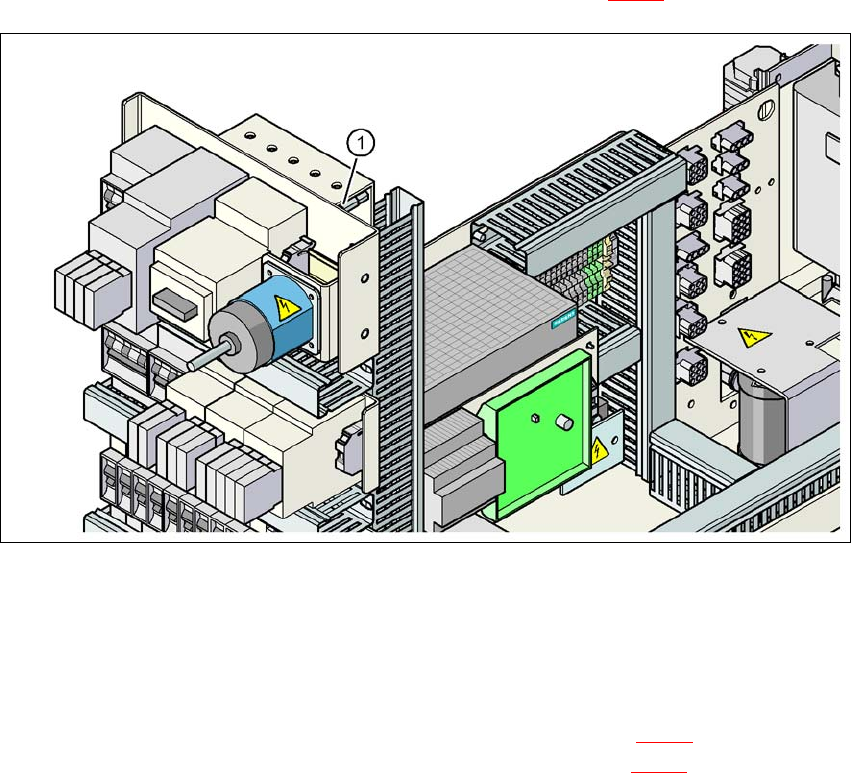
4.2.4.6 Checking the inrush current limitation jumpers
The inrush current limitation must be configured in relation to the supply voltage. This is done us-
ing wire jumpers on the inrush current limitation board (item 1 in Fig. 4.2 - 7
).
4
Fig. 4.2 - 7 Position of the board and connectors for the inrush current limitation
(1) Inrush current limitation board
→ Check the jumper assignment and correct if necessary.
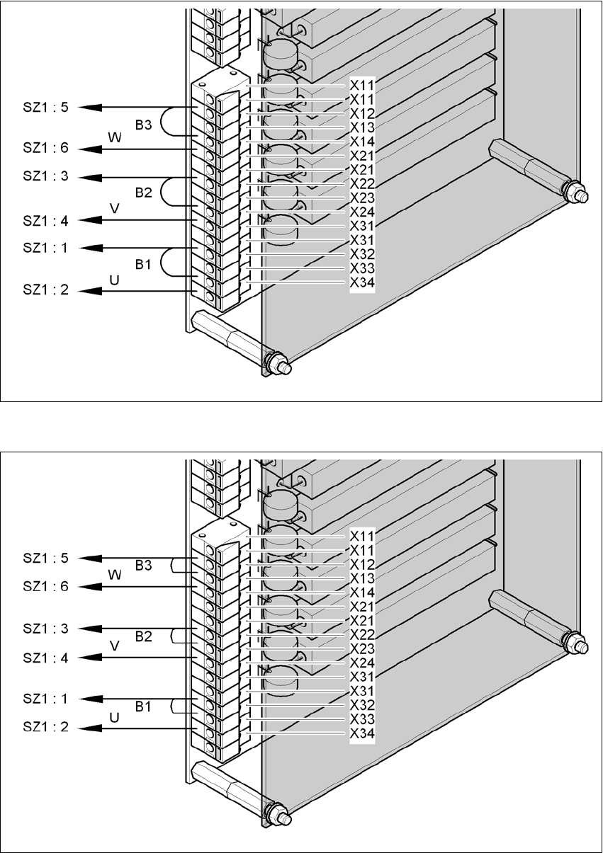
Supply voltage 3 x 200 VAC / 3 x 208 VAC / 3 x 230 VAC (see Fig. 4.2 - 8
)
Supply voltage 3 x 380 VAC / 3 x 400 VAC / 3 x 415 VAC (see Fig. 4.2 - 9
) 4
User manual SIPLACE D4 4 Setting up and commissioning
From software version SR.605.xx 07/2008 EN Edition 4.2 Infrastructure at the installation location
163
4
Fig. 4.2 - 8 Inrush current limitation - connections and jumpers at 3 x 200 VAC / 3 x 208 VAC / 3 x 230 VAC
4
Fig. 4.2 - 9 Inrush current limitation - connections and jumpers at 3 x 380 VAC / 3 x 400 VAC / 3 x 415 VAC
3 x 200 VAC / 3 x 208 VAC / 3 x 230
3 x 380 VAC / 3 x 400 VAC / 3 x 415 VAC