00195779-0102_UM_D4_SR605_EN.pdf - 第168页
4 Setting up and commissioning User manual SIPLACE D4 4.3 Setting up the machine From software version SR.605.xx 07/2008 EN Edition 168 4 Fig. 4.3 - 2 Machine feet (1) Outer machine foot , 4x (2) S pacer (3) Middle machi…
User manual SIPLACE D4 4 Setting up and commissioning
From software version SR.605.xx 07/2008 EN Edition 4.3 Setting up the machine
167
4
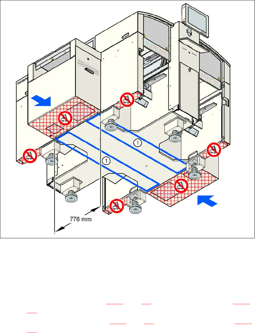
Fig. 4.3 - 1 Contact surfaces - Forks parallel to the direction of PCB transport
(1) Contact surfaces for the forks of the fork-lift
4
→ With the fork-lift, raise the machine approximately 35 cm.
The machine stands on 6 feet.
– 4 outer machine feet (item 1 in Fig. 4.3 - 2
, page 168) with 4 spacers (item 2 in Fig. 4.3 - 2,
page 168
) for adjusting the height, if necessary.
– 2 middle machine feet (item 3 in Fig. 4.3 - 2
, page 168) with 2 spacers (item 2 in Fig. 4.3 - 2,
page 168
) for adjusting the height, if necessary.
4 Setting up and commissioning User manual SIPLACE D4
4.3 Setting up the machine From software version SR.605.xx 07/2008 EN Edition
168
4
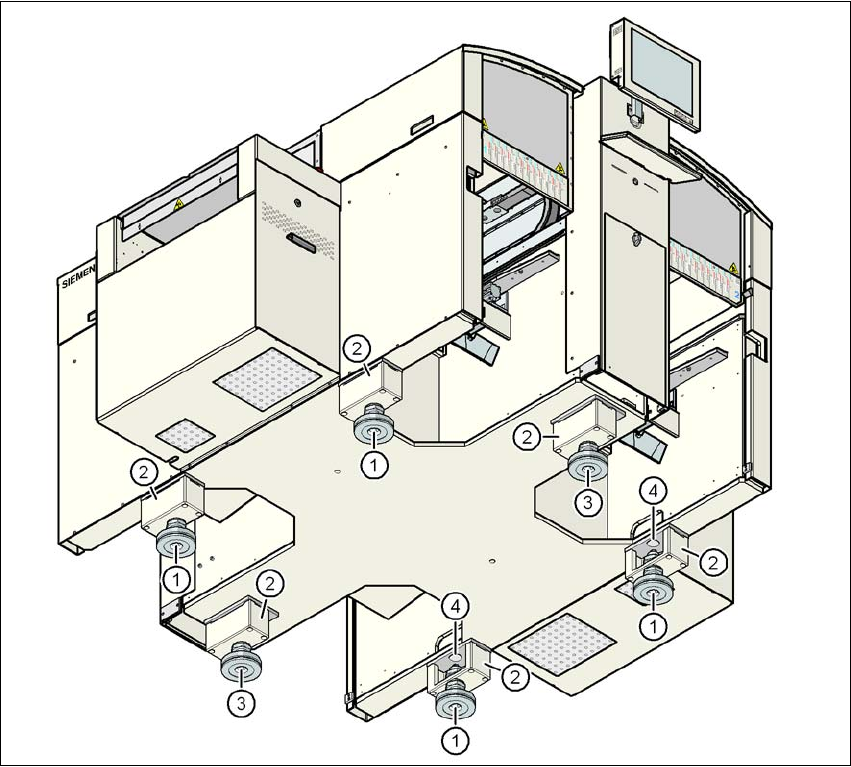
Fig. 4.3 - 2 Machine feet
(1) Outer machine foot, 4x
(2) Spacer
(3) Middle machine foot, 2x
(4) Hole in the machine frame for the machine foot for the 830 mm PCB conveyor height

User manual SIPLACE D4 4 Setting up and commissioning
From software version SR.605.xx 07/2008 EN Edition 4.3 Setting up the machine
169
4.3.4.1 Spacers for the PCB conveyor heights of 900 / 930 / 950 mm
There are different spacers (see item 2 in Fig. 4.3 - 2) and fixing screws for the 900 / 930 / 950
mm PCB conveyor height. You will need 6 spacers and 24 fixing screws.
4.3.4.2 Presetting the PCB conveyor height to 830 mm
You will not need a spacer for a PCB conveyor height of 830 mm.
→ Insert the machine feet into the holes in the machine frame (item 4 in Fig. 4.3 - 2
, page 168).
→ Use the M24 nuts to set the height of the outer machine feet (item 1 in Fig. 4.3 - 2
, page 168)
so that the distance between the underside of the machine foot and the bottom edge of the
machine frame is 110 mm.
→ Hand-tighten the M24 nuts.
→ First set the middle machine feet (item 3 in Fig. 4.3 - 2
, page 168) to a height of around 100
mm.
4.3.4.3 Presetting the PCB conveyor height to 900 / 930 / 950 mm
→ Then fix the 6 spacers (item 2 in Fig. 4.3 - 2, page 168).
The spacers for the different PCB conveyor heights are listed in Section 4.3.4.1
, page 169.
→ Use the M24 nuts to set the height of the outer machine feet (item 1 in Fig. 4.3 - 2
, page 168)
to the following values:
PCB conveyor
height
Spacer, 6x
Item no.
Spacer
Height
Hexagon socket
head screw, 24x
830 mm – – –
900 mm 00344069-xx 70 mm DIN 912 M12x70
930 mm 00344070-xx 100 mm DIN 912 M12x100
950 mm 00331553-xx 122.5 mm DIN 912 M12x100
PCB conveyor height Distance from underside of outer machine foot to
bottom edge of machine frame
900 mm 183 mm
930 mm 213 mm
950 mm 235 mm