00195779-0102_UM_D4_SR605_EN.pdf - 第198页
5 Tasks for the operating personnel User manual SIPLACE D4 5.2 Controls and displays From software version SR.605.xx 07/2008 EN Edition 198 5.2.2 Description All the contr ols can be re ached by a 1.40 m tall person. Mai…
User manual SIPLACE D4 5 Tasks for the operating personnel
From software version SR.605.xx 07/2008 EN Edition 5.2 Controls and displays
197
5.2 Controls and displays
5.2.1 Position
5
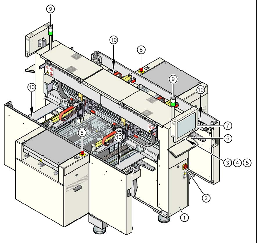
Fig. 5.2 - 1 Controls and displays
(1) Operator panel on the power supply side (7) LCD touchscreen
(2) Main power switch (8) EMERGENCY STOP button
(3) Stop button (black) (9) Indicator lamps
(4) Start button (white) (10) Button for raising the CO table
(beneath the cover flap)
(5) Component counter
(6) Keyboard
5 Tasks for the operating personnel User manual SIPLACE D4
5.2 Controls and displays From software version SR.605.xx 07/2008 EN Edition
198
5.2.2 Description
All the controls can be reached by a 1.40 m tall person.
Main power switch 5
The main power switch is used to switch the power supply to the machine on and off.
WARNING
Some parts inside the machine carry potentially lethal voltages - even when switched off at the
main power switch. 5
Stop button 5
This button is used to stop the machine.
Start button 5
This button starts the machine after it has been switched on or after faults have been eliminated.
EMERGENCY STOP button 5
The EMERGENCY STOP button latches in the ON position when pressed. The power supply to
the gantry axes, the component trolleys, conveyors and used tape cutters is interrupted and the
voltage supplied to the star axes of the placement heads is reduced. Turn the button to release it.
Component counter 5
The component counter displays the number of components processed in increments of ten.
LCD touchscreen 5
There is a flat screen on either side of the machine.
Keyboard 5
The keyboard is located beneath the monitor.
Indicator lamps 5
The sequence of colors of the indicator lamps is white - green. These lamps are used to signal
operating statuses and malfunctions of the machine.

User manual SIPLACE D4 5 Tasks for the operating personnel
From software version SR.605.xx 07/2008 EN Edition 5.2 Controls and displays
199
5.2.3 Ergonomic arrangement of the controls
Figure 5.2 - 1 on page 197 provides an overview of the position of the controls. They are subdi-
vided into the following groups:
Operator panel on the right-hand side (pneumatic unit) of the center console with 5
– LCD touchscreen
– Keyboard with trackball
– Start button, stop button
Operator panel on the left-hand side (power supply unit) of the center console with 5
– LCD touchscreen
– Keyboard with trackball
– Component counter
– Start button
– Stop button
– Main power switch
Input / output side of the PCB conveyor with 5
– EMERGENCY STOP button
– Start button, stop button
5.2.3.1 Controls on the machine's operator panels
The two operator panel have identical control functions.
Monitor, keyboard, start and stop buttons 5
There is a monitor and a keyboard on both sides of the machine.
The start and stop buttons are located beneath the keyboard. The on-screen dialog will occasion-
ally prompt you to activate certain actions using buttons, and this arrangement will make it easier
for you both to activate and to interactively control these actions.
Main power switch 5
The main power switch is part of the power module. It is located on the left-hand operator panel
viewed in the direction of PCB transport. It is located here because it is only needed for servicing
and preventive maintenance work and is therefore not subject to frequent use.