00195779-0102_UM_D4_SR605_EN.pdf - 第201页
User manual SIPLACE D4 5 Tasks for the operating personnel From software version SR.605.xx 07/2008 EN Edition 5.3 Note operating status indicator lamp 201 5.3.2 General operating statuses – Operating status indicato r la…
5 Tasks for the operating personnel User manual SIPLACE D4
5.3 Note operating status indicator lamp From software version SR.605.xx 07/2008 EN Edition
200
5.2.3.2 Controls on the input and output sides of the machine
The controls on the input and output sides of the machine perform identical functions.
EMERGENCY STOP buttons, start and stop buttons 5
There is an EMERGENCY STOP button and start and stop buttons on both the input and output
sides of the PCB conveyor. This arrangement was adopted for the buttons because it enables
them to be reached quickly and easily from any position.
5.3 Note operating status indicator lamp
The indicator lamp is used to signal operating statuses and malfunctions of the machine.
5.3.1 Description of the functions
5
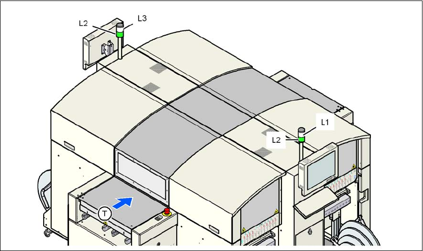
Fig. 5.3 - 1 Operating status indicator lamp
L1 Fault indicator lamp (white, right)
L2 Operating status indicator lamp (green, both lamps switched in parallel)
L3 Fault indicator lamp (white, left)
T Direction of PCB transport

User manual SIPLACE D4 5 Tasks for the operating personnel
From software version SR.605.xx 07/2008 EN Edition 5.3 Note operating status indicator lamp
201
5.3.2 General operating statuses
– Operating status indicator lamp L2 (green) on continuously
The machine is in service.
– Operating status indicator lamp L2 (green) flashes
The machine is waiting for a PCB on the input belt or the machine is waiting until the output
belt is free.
– Right fault indicator lamp L1 (white) flashes
One or more tracks are empty on the right-hand side of the machine. The machine populates
the current PCB with the existing components.
– Left fault indicator lamp L3 (white) flashes
One or more tracks are empty on the left-hand side of the machine. The machine populates
the current PCB with the existing components.
– Right fault indicator lamp L1 (white ) on continuously - operating status lamp L2 (green) off
An error has occurred on the right-hand side of the machine -> the machine has stopped.
– Left fault indicator lamp L3 (white ) on continuously - operating status lamp L2 (green) off
An error has occurred on the left-hand side of the machine -> the machine has stopped.
– Both fault indicator lamps L1 and L3 (white) on continuously - operating status lamp L2
(green) off
An error has occurred that affects the entire machine -> the machine has stopped.
5
5
5.3.3 Programmed operating status displays
The following table shows the programmed operating status displays in the standard configuration
(version as supplied) and lists their meaning on the individual lamps of the main fault indicator.
The entries in the table next to "flashes" refer to the frequency with which the relevant lamp flashes
for a given event. The entry (1, 5), for example, can be explained as follows:
– The first number in the brackets indicates the time, expressed in 100 msec. intervals, for
which the fault indicator lamp is switched on, i.e. 1 x 100 ms in the above example.
– The second number in the brackets indicates the time, expressed in 100 msec. intervals, for
which the fault indicator lamp is switched off, i.e. 5 x 100 ms in the above example.
5
L1 (white)
(right lamp)
L2 (green) L3 (white)
(left lamp)
Meaning
Status display
flashes (1,10) flashes (7,7) flashes (1,10) Reference run
unchanged flashes (1,5) unchanged Waiting until axes in position

5 Tasks for the operating personnel User manual SIPLACE D4
5.3 Note operating status indicator lamp From software version SR.605.xx 07/2008 EN Edition
202
unchanged flashes (7,7) unchanged Waiting for setup data
unchanged flashes (7,7) unchanged Waiting for cluster data
unchanged flashes (7,7) unchanged Load table program
unchanged flashes (7,7) unchanged Position detection
unchanged flashes (1,10) unchanged Bad fiducial detection
unchanged flashes (7,7) unchanged Nozzle configuration test
unchanged flashes (7,7) unchanged Feeder position detection
unchanged flashes (7,7) unchanged One track is empty
unchanged flashes (7,7) unchanged No further track available
unchanged flashes (7,7) unchanged Go to refill position
unchanged flashes (7,7) unchanged Transport being initialized
unchanged flashes (7,7) unchanged Place PCB in input conveyor
flashes (1,10) flashes (7,7) unchanged Remove PCB from output conveyor
unchanged flashes (7,7) flashes (1,10) Remove PCB from output conveyor 2
flashes (1,10) flashes (7,7) flashes (1,10) Width adjustment
unchanged flashes (1,10) unchanged Transport PCB
flashes (1,10) flashes (7,7) flashes (1,10) Both output conveyors are cleared
on flashes (1,10) on Conveyor error
on off on Go to service position
on Placement
flashes (1,20) Waiting for processing data
Error display
on off unchanged Machine error, right
on off unchanged Track empty, right
on off unchanged Nozzle configuration, right
on off unchanged Conveyor error, right
on off on Fiducial error, left and right
on off on Fiducial error, left and right
unchanged off on Track empty, left
unchanged off on Nozzle configuration, left
unchanged off on Conveyor error, left
unchanged off on Machine error, left
L1 (white)
(right lamp)
L2 (green) L3 (white)
(left lamp)
Meaning