00195779-0102_UM_D4_SR605_EN.pdf - 第215页
User manual SIPLACE D4 5 Tasks for the operating personnel From software version SR.605.xx 07/2008 EN Edition 5.9 Refilling components 215 5.9 Refilling component s The online help contai ns information on refilling comp…
5 Tasks for the operating personnel User manual SIPLACE D4
5.8 Avoiding track errors From software version SR.605.xx 07/2008 EN Edition
214
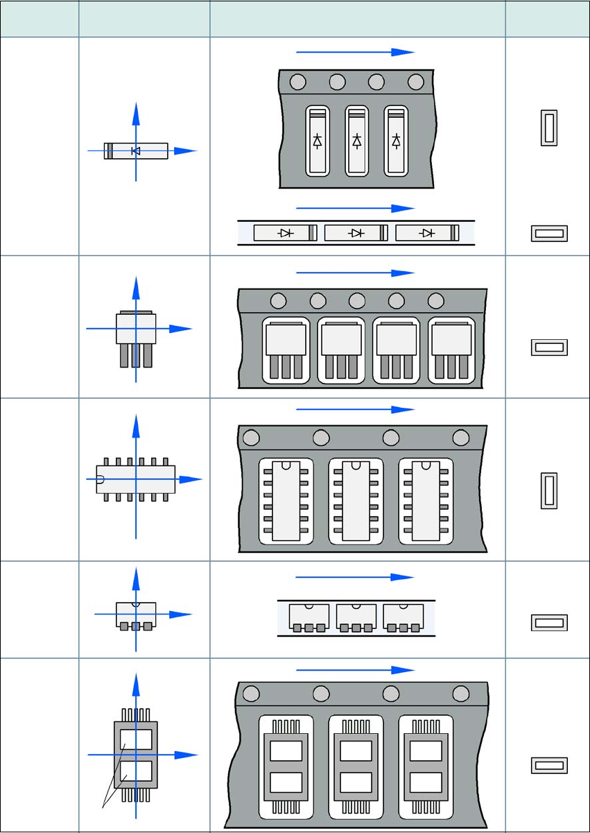
5.8.3 Component coordinate system and pick-up angle
5
Fig. 5.8 - 1 Position of the component and its pick-up angle
Special
component
Stick
magazine:
Chip-
components
with polarity
0402
2220
The anode must be
aligned with the +X
coordinate.
Package form Coordinate system
Position in the feeder module
Pick-up angle/
nozzle angle
Tape:
SOT 23
Stick
magazine:
Tape:
Tape:
SO-IC
DIL-IC
SOT 194
Tape:
Holes
Y
X
Y
X
Y
X
Y
X
Y
X
90°
90°
0°
90°
-90°
0°

User manual SIPLACE D4 5 Tasks for the operating personnel
From software version SR.605.xx 07/2008 EN Edition 5.9 Refilling components
215
5.9 Refilling components
The online help contains information on refilling components with and without barcodes.
→ With tape feeder modules, make sure that you always splice on a new tape early enough so
that the feeder modules do not run out of components.
→ However, do not splice the tapes too early because if you wind the tape onto the new reel
after splicing the end of the old tape, the reel with the new tape may be overfilled. The tape
could then slip off the reel and become tangled. Under certain circumstances, this could
cause pick-up errors and prolonged down times.
→ Always insert spindles when using tape reels of 15" (381 mm) and larger (see Fig. 5.5 - 3
,
page 208
) and make sure that the separating plates are inserted correctly (see Fig. 5.5 - 2,
page 207
).
5 Tasks for the operating personnel User manual SIPLACE D4
5.10 Docking the component trolley in or out From software version SR.605.xx 07/2008 EN Edition
216
5.10 Docking the component trolley in or out
WARNING 5
→ Please follow the safety instructions for docking the component trolley in and out described
in Section 2.5.2, page 52.
5.10.1 Docking out the component trolley
→ Click on the STOP PROCESSING PCB icon in the MAIN VIEW menu.
The PCB in progress will be completed. The icons of the single functions menu will then be
activated. 5
→ Click on the desired icon SINGLE FUNCTIONS GANTRY.
→ Select GANTRY FUNCTIONS.
→ From this menu, click on the GO TO SET-UP POSITION button.
All the placement heads will move across the PCB conveyor to prevent them being damaged
when the component trolley is changed. 5
→ Open the protective cover of the selected gantry.
→ Open the cover over the button for the lifting mechanism for the component table bed (see
Fig. 5.10 - 1
, item 1, page 217).
WARNING DANGER OF CRUSHING 5
When raising the component table bed, never reach into the gap between the feeders and
the used tape channel. 5
→ Turn the switch on the component table (item 4 in Fig. 5.10 - 1
, page 217) up.
→ Press the button until the component table bed (item 8 in Fig. 5.10 - 1
, page 217) has reached
the upper final position.
→ Unplug the supply cable of the component trolley from the socket on the station (item 2 in Fig.
5.10 - 1
, page 217).
→ Swivel the two handles up (item 1 in Fig. 5.10 - 2
, page 218).