00195779-0102_UM_D4_SR605_EN.pdf - 第237页
User manual SIPLACE D4 6 Station extensions From software version SR.605.xx 07/2008 EN Edition 6.4 SMEMA adapter box 237 The PCB is transported into the placement ar ea un til the laser light barrie r trig gers the stop …
6 Station extensions User manual SIPLACE D4
6.3 PCB alignment From software version SR.605.xx 07/2008 EN Edition
236
6.3 PCB alignment
Item no. 00119425-xx PCB alignment for single conveyor
Item no. 00119426-xx PCB alignment for dual conveyor
6.3.1 Description
PCBs to be processed sometimes have a length to width ratio of 1:2 or worse. This means that
the shorter side of the PCB points in the direction of travel. During travel, such PCBs may twist
slightly and, as a result, the fiducials no longer lie within the PCB camera's search window. In this
case, the "PCB alignment" option ensures that these PCBs are realigned precisely at the stopping
position.
If PCBs with recesses in the direction of travel are processed, this may result in different process-
ing positions on machines that monitor this position with laser light barriers (X-series, D-series).
The "PCB alignment" option ensures that the PCBs are stopped at the required position on the
PCB conveyors. The "PCB alignment" option is available for both single and dual conveyors.
6
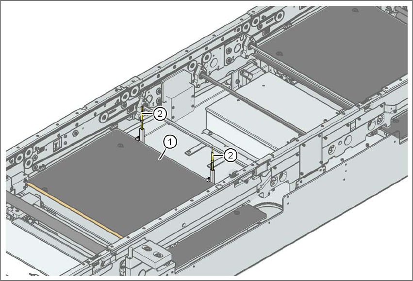
Fig. 6.3 - 1 PCB alignment
(1) Lifting table
(2) PCB stop

User manual SIPLACE D4 6 Station extensions
From software version SR.605.xx 07/2008 EN Edition 6.4 SMEMA adapter box
237
The PCB is transported into the placement area until the laser light barrier triggers the stop signal
for the PCB conveyor. The lifting table with the PCB stops then moves up into a position in which
the PCB is not yet clamped and can still be moved by the conveyor belts. The two PCB stops are
level with the PCB, and the PCB supports (magnetic pins) are already in contact with the PCB.
The two conveyor belts move the PCB against the PCB stops and align them at the same time.
The lifting table then moves into its top end position, clamps the PCB and releases it from the PCB
stops so as not to affect the placement process. After the placement process, the lifting table and
PCB alignment are lowered and the PCB is moved on.
6
6.4 SMEMA adapter box
Item no. 00119092-xx SMEMA adapter box D4/D2/D1
The PCB conveyor control for the D series of machines has the Siemens interface for communi-
cation between machines. You can configure the conveyor interface to the SMEMA standard us-
ing the SMEMA adapter box and the associated cable sets.
More detailed information can be found in the "Siemens conveyor interface retrofit instructions",
item no. 00194343-xx.
6.5 Package for splice detection
Item no. 00119032-xx Splice detection, D4 table controller
Item no. 00116938-xx Splice detection, D4 station package
Item no. 00141xxx-xx Splice sensors for S tape feeder modules
(see Section 3.9.7
, page 122 for item numbers)
Splice detection serves to recognize a batch change for components. The component tapes are
attached to the splicing point by a metal strip. The component tape runs over the splice sensor
which is installed on the feeder module and signalizes a tape change.

6 Station extensions User manual SIPLACE D4
6.6 Long board From software version SR.605.xx 07/2008 EN Edition
238
6.6 Long board
Item no. 00119427-xx Long board option, single conveyor
Item no. 00119428-xx Long board option, dual conveyor
a
Item no. 00119631-xx Conveyor width 242/508 mm (Wide board), D1/D2/D3/D4
The following PCB formats can be placed on D4 machines:
6
6
We can supply the Long board option as a retrofit kit for placing PCBs that are over 368 mm long.
If the Long board option is installed, then the following PCB formats can be processed:
6
6
The retrofit kit consists of the following parts:
– Complete mechanism: stopper, sensors, cables and assembly parts
– Optional CD for enabling the function on the SIPLACE Pro computer
– Retrofit instructions
More detailed information can be found in the Long board retrofit instructions, item no. 00193888-
01.
a) When ordering for the dual conveyor, also quote the item number 00119428-xx in addition to the item number
00119427-xx.
Single conveyor (standard width) 50 x 50 mm² to 368 x 460 mm²
Single conveyor, Wide board 50 x 50 mm² to 368 x 508 mm²
Dual conveyor (standard width) 50 x 50 mm² to 368 x 216 mm²
Dual conveyor, Wide board 50 x 50 mm² to 368 x 242 mm²
Dual conveyor in Single conveyor mode 50 x 50 mm² to 368 x 380 mm²
Single conveyor, Long board (standard width) 50 x 110 mm² to 610 x 460 mm²
Single conveyor, Wide board, Long board 50 x 110 mm² to 610 x 508 mm²
Dual conveyor, Long board (standard width) 50 x 120 mm² to 610 x 216 mm²
Dual conveyor, Wide board, Long board 50 x 120 mm² to 610 x 242 mm²
Dual conveyor in Single conveyor mode, Long board (stan-
dard width)
50 x 120 mm² to 610 x 380 mm²