00195779-0102_UM_D4_SR605_EN.pdf - 第242页
6 Station extensions User manual SIPLACE D4 6.8 Component sensor for the C&P12 head From software ver sion SR.605.xx 07/2008 EN Edition 242 PLEASE NOTE 6 If you are placing 0201 componen t s with the 906 nozzle, it i…
User manual SIPLACE D4 6 Station extensions
From software version SR.605.xx 07/2008 EN Edition 6.8 Component sensor for the C&P12 head
241
6.8.1 Description
The component sensor is fixed to the bottom of the housing of the 12-segment Collect&Place
head (see Fig. 6.8 - 1
, page 240). It scans the outline of a component and checks whether there
is a component at the nozzle. It also determines the height of the component. This data can be
used to determine whether the component is in the normal position or on edge at the nozzle. Com-
ponent heights from 0.1 to 4 mm can be checked. For larger components, only the presence of
the component at the nozzle is checked.
The component sensor is configured in the package form editor on the SIPLACE Pro computer.
Every nozzle, including the special nozzles, can be scanned by the component sensor.
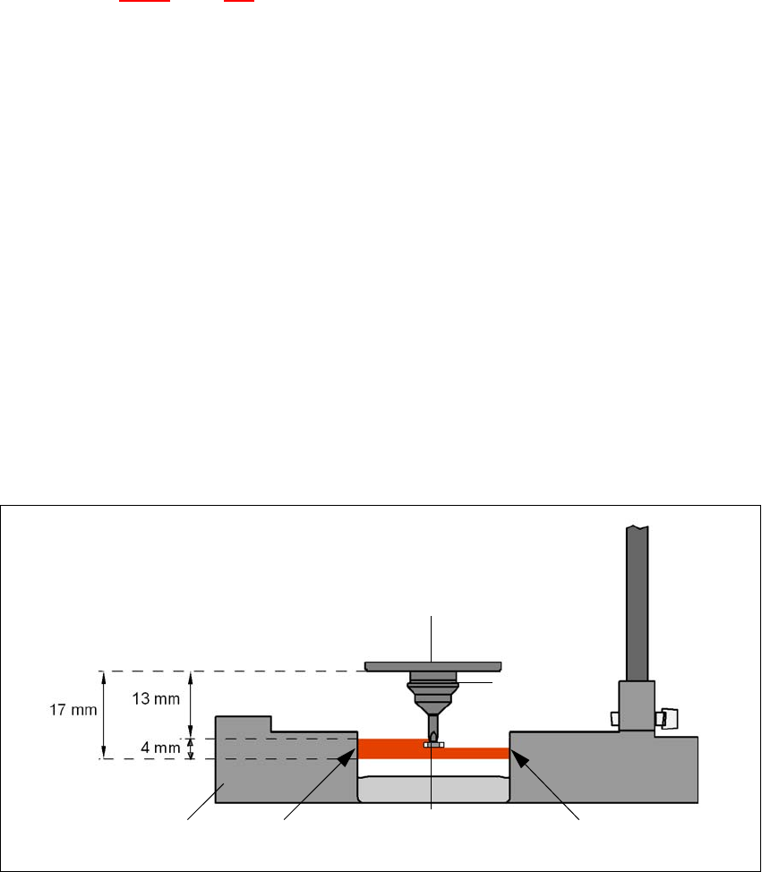
6.8.2 Measuring conditions
The two following conditions must be fulfilled in order to obtain a valid measurement:
– The light beam must touch the empty nozzle tip during the calibration process.
– The nozzle tip must be inside the light beam when it is holding a component.
– Minimum nozzle length 13 mm
– Nozzle length + component height + tolerance < 17 mm
If these conditions are fulfilled, it is possible to determine whether a component is present or ab-
sent, or to measure the component height. The minimum difference in height is 100 µm.
6
Fig. 6.8 - 2 Component sensor, working principle
Incremental disk
Component
Nozzle
IR LED PhototransistorCross-section through
component sensor

6 Station extensions User manual SIPLACE D4
6.8 Component sensor for the C&P12 head From software version SR.605.xx 07/2008 EN Edition
242
PLEASE NOTE 6
If you are placing 0201 components with the 906 nozzle, it is essential to use the component sen-
sor since no vacuum measurements are possible. 6
Using the component sensor can improve the dpm rate even when placing other small compo-
nents, such as 0402 or 0603 components. When you select a component sensor from the pack-
age form list, remember that the component can only be placed on machines that are equipped
with that component sensor.
If you wish to test components with the component sensor, then it must be configured on the line.
The following alternatives are then available:
New set-up The set-up optimization automatically assigns the components to the
component sensor, if the sensor is installed.
Old set-up A new GF number is assigned to components to be checked with the
component sensor.
Central data management If not every machine on the line is equipped with the component sen-
sor, then a new package form number is assigned for every compo-
nent to be checked with the component sensor.
PLEASE NOTE 6
– The component sensor may only be retrofitted by SIPLACE service engineers.
– Recalibrate the 12-segment C&P head with the SITEST program after installing the component
sensor.
User manual SIPLACE D4 6 Station extensions
From software version SR.605.xx 07/2008 EN Edition 6.9 C&P high-resolution CO camera, type 29, 27 x 27, digital
243
6.9 C&P high-resolution CO camera, type 29, 27 x 27, digital
Item no. 00119779-xx High-resolution camera, C&P12, digital
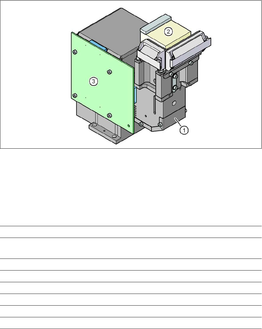
6.9.1 Structure
6
Fig. 6.9 - 1 C&P component camera, type 29, 27 x 27, digital
(1) Component camera lens and illumination
(2) Camera amplifier
(3) Illumination control
6.9.2 Technical data
6
Component dimensions 0.3 x 0.3 mm² to 18.7 x 18.7 mm²
Range of components 0201 to 27 x 27 mm²
PLCC, SO, QFP, TSDP, SOT, MELF, CHIP, IC BGA
Min. lead pitch 0.3 mm
Min. lead width 0.15 mm
Min. ball pitch 0.25 mm
Min. ball diameter 0.14 mm
Field of vision 32 x 32 mm²
Method of illumination Front-illumination (5 levels, programable as required)