00195779-0102_UM_D4_SR605_EN.pdf - 第243页
User manual SIPLACE D4 6 Station extensions From software version SR.605.xx 07/2008 EN Edition 6.9 C &P high-resolution CO camera, type 29, 27 x 27, digital 243 6.9 C&P high-resolution CO came ra, type 29, 27 x 2…

6 Station extensions User manual SIPLACE D4
6.8 Component sensor for the C&P12 head From software version SR.605.xx 07/2008 EN Edition
242
PLEASE NOTE 6
If you are placing 0201 components with the 906 nozzle, it is essential to use the component sen-
sor since no vacuum measurements are possible. 6
Using the component sensor can improve the dpm rate even when placing other small compo-
nents, such as 0402 or 0603 components. When you select a component sensor from the pack-
age form list, remember that the component can only be placed on machines that are equipped
with that component sensor.
If you wish to test components with the component sensor, then it must be configured on the line.
The following alternatives are then available:
New set-up The set-up optimization automatically assigns the components to the
component sensor, if the sensor is installed.
Old set-up A new GF number is assigned to components to be checked with the
component sensor.
Central data management If not every machine on the line is equipped with the component sen-
sor, then a new package form number is assigned for every compo-
nent to be checked with the component sensor.
PLEASE NOTE 6
– The component sensor may only be retrofitted by SIPLACE service engineers.
– Recalibrate the 12-segment C&P head with the SITEST program after installing the component
sensor.
User manual SIPLACE D4 6 Station extensions
From software version SR.605.xx 07/2008 EN Edition 6.9 C&P high-resolution CO camera, type 29, 27 x 27, digital
243
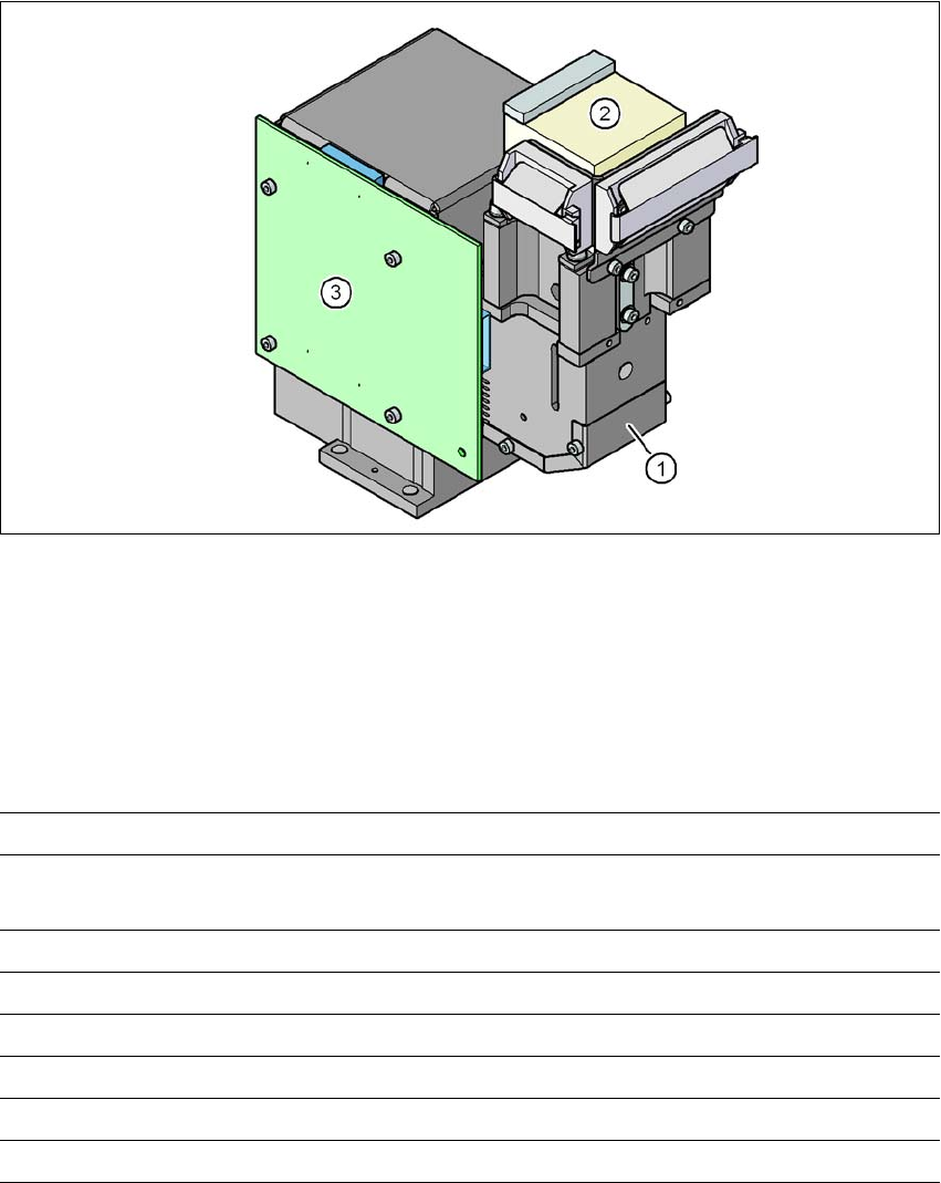
6.9 C&P high-resolution CO camera, type 29, 27 x 27, digital
Item no. 00119779-xx High-resolution camera, C&P12, digital
6.9.1 Structure
6
Fig. 6.9 - 1 C&P component camera, type 29, 27 x 27, digital
(1) Component camera lens and illumination
(2) Camera amplifier
(3) Illumination control
6.9.2 Technical data
6
Component dimensions 0.3 x 0.3 mm² to 18.7 x 18.7 mm²
Range of components 0201 to 27 x 27 mm²
PLCC, SO, QFP, TSDP, SOT, MELF, CHIP, IC BGA
Min. lead pitch 0.3 mm
Min. lead width 0.15 mm
Min. ball pitch 0.25 mm
Min. ball diameter 0.14 mm
Field of vision 32 x 32 mm²
Method of illumination Front-illumination (5 levels, programable as required)
6 Station extensions User manual SIPLACE D4
6.10 01005 package From software version SR.605.xx 07/2008 EN Edition
244
6.10 01005 package
Item no. 00119920-xx 01005 package for D4/D2/D1
The SIPLACE D4 machine is already prepared to place 01005 components. In order to process
01005-BE one simply needs upgrading of the 12-segment Collect&Place head. The retrofitting
package contains the following parts:
– CO camera, C&P, type 38, 16 x 16, digital Item no. 03051870-xx, 1x
– A type 12 sleeve complete, 270°-sub-division Item no. 03054107-xx, 3x
– Nozzle, type 905 ESD, 1 x 0.15 Item no. 03057320-xx, 12x
– Assembly instructions 01005 package for D4/D2/D1
German and EnglishItem no. 00195398-xx, 1 piece
6.11 0201 package
Item no. 00119720-xx 0201 package for C&P12, X/D series
We can supply the 0201 package for processing 0201 components with the 12-segment Col-
lect&Place head.
This contains:
– C&P component camera (type 29), 27 x 27, digital, item no. 00119779
– Component sensor for the 12-segment C&P head, item no. 00118021
– 12 nozzles, type 706/906 Vectra ceramic, item no. 00345031