00195779-0102_UM_D4_SR605_EN.pdf - 第246页
6 Station extensions User manual SIPLACE D4 6.13 SIPLACE Productivity Lift From software version SR.605.xx 07/2008 EN Edition 246 6.13 SIPLACE Productivity Lif t 6.13.1 Concept of p arallel placement Placement lines are …

User manual SIPLACE D4 6 Station extensions
From software version SR.605.xx 07/2008 EN Edition 6.12 Vacuum pump
245
6.12 Vacuum pump
Item no. 00119017-xx Vacuum pump
Item no. 00119406-xx Connection kit for vacuum pump
Every Collect&Place head has a separate vacuum generator that supplies the holding and place-
ment circuit with the vacuum that it needs. The vacuum generator works on the Venturi principle.
The machine's compressed air consumption is approximately 950 Nl/min, which means that the
compressed air supply must be dimensioned accordingly. If the owner does not have sufficient ca-
pacity locally, the associated investment costs would be high, so we supply a vacuum pump that
will provide the necessary vacuum.
Other advantages of using the vacuum pump are:
– It roughly halves the machine's compressed air consumption.
– It reduces the input pressure.
– The machine can be easily integrated into existing lines.
– The ongoing operating costs reduce according to the energy costs.
The vacuum pump is maintenance-free and 100% oil-free. It has sufficient capacity to supply the
holding circuits of the Collect&Place heads.
Compressed air consumption of the machine
a
a) Under normal atmospheric conditions at 20°C and 1013 hPa
Without vacuum pump 950 Nl/min
With vacuum pump 400 Nl/min
6 Station extensions User manual SIPLACE D4
6.13 SIPLACE Productivity Lift From software version SR.605.xx 07/2008 EN Edition
246
6.13 SIPLACE Productivity Lift
6.13.1 Concept of parallel placement
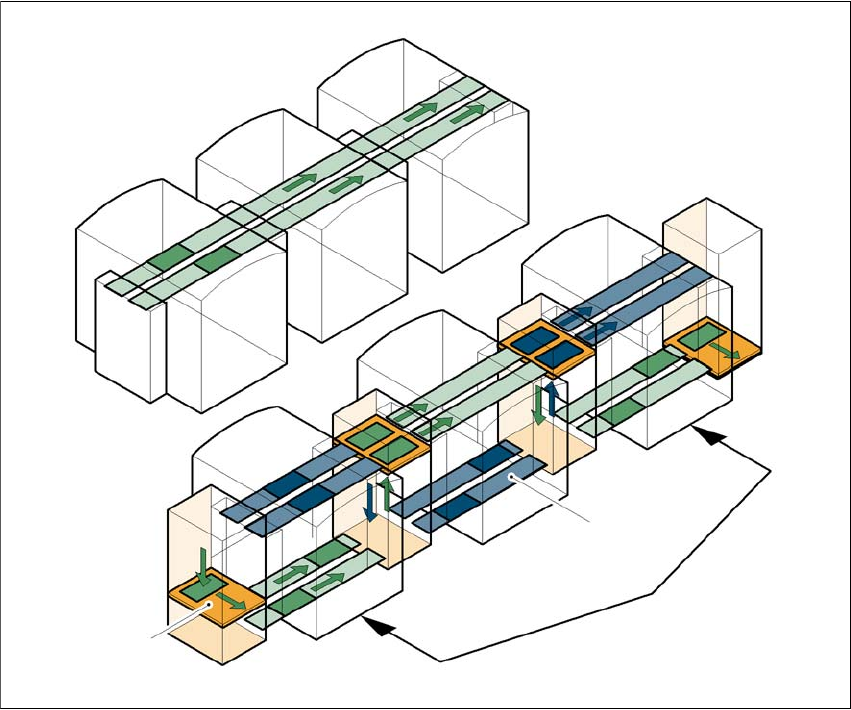
Placement lines are generally arranged in series and are linked to one another serially. The place-
ment program is processed sequentially while the PCBs are transported from one machine to the
next. This means that the placement of a PCB is distributed between various machines.
6
Fig. 6.13 - 1 A comparison of serial and parallel lines
When machines are connected in parallel, the components to be placed by individual machines
are combined. Several machines work through the same placement program. They place all the
components on one machine that would be distributed between several machines with serial pro-
cessing. When one machine runs out of capacity, the PCBs are moved to and placed at the next
machine with the same placement program. This combination of machines with the same compo-
nents to be placed is known as a group or “cluster”.
Serial line
Parallel line
Underfloor conveyor
Group (cluster)
Horizontal/
vertical lift
User manual SIPLACE D4 6 Station extensions
From software version SR.605.xx 07/2008 EN Edition 6.13 SIPLACE Productivity Lift
247
6.13.2 Implementing parallel placement
Lines with machines arranged in parallel take up a lot more space, so the parallel placement con-
cept was implemented with an underfloor conveyor and horizontal / vertical lift (HV shuttle). The
machines are still arranged in series, but the lift units and underfloor conveyors allow the line to
be operated in parallel. In this way, SIPLACE lines remain almost as compact as before.
Underfloor conveyor 6
Two conveyor belts carry empty or placed PCBs underneath the machines (see Fig. 6.13 - 1, page
246
).
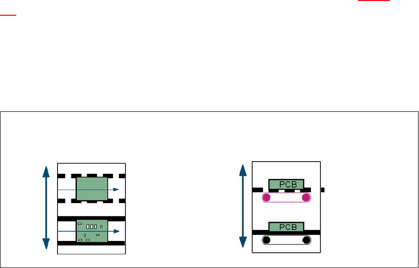
Horizontal/vertical lift (horizontal/vertical shuttle) 6
There is an HV shuttle at the start of a line, between the machines and at the end of the line. It
carries the PCBs between the underfloor and processing levels, and between the two tracks on
the underfloor conveyors.
6
Fig. 6.13 - 2 Horizontal / vertical shuttle (HV shuttle), conveyor track change and lift function
Horizontal conveyor
HV shuttle
Lift function
Vertical conveyor
Unplaced
Placed
Standard
conveyor level
Underfloor
conveyor level
HV shuttle
Conveyor track change