00195779-0102_UM_D4_SR605_EN.pdf - 第247页
User manual SIPLACE D4 6 Station extensions From software version SR.605.xx 07/2008 EN Edition 6.13 SIPLACE Productivity Lift 247 6.13.2 Implementing p arallel placement Lines with machines arranged in p arallel take up …
6 Station extensions User manual SIPLACE D4
6.13 SIPLACE Productivity Lift From software version SR.605.xx 07/2008 EN Edition
246
6.13 SIPLACE Productivity Lift
6.13.1 Concept of parallel placement
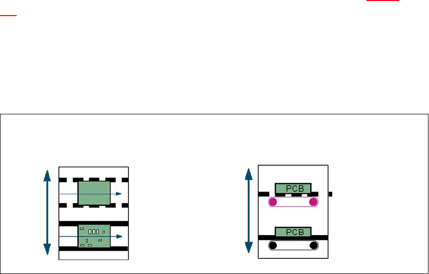
Placement lines are generally arranged in series and are linked to one another serially. The place-
ment program is processed sequentially while the PCBs are transported from one machine to the
next. This means that the placement of a PCB is distributed between various machines.
6
Fig. 6.13 - 1 A comparison of serial and parallel lines
When machines are connected in parallel, the components to be placed by individual machines
are combined. Several machines work through the same placement program. They place all the
components on one machine that would be distributed between several machines with serial pro-
cessing. When one machine runs out of capacity, the PCBs are moved to and placed at the next
machine with the same placement program. This combination of machines with the same compo-
nents to be placed is known as a group or “cluster”.
Serial line
Parallel line
Underfloor conveyor
Group (cluster)
Horizontal/
vertical lift
User manual SIPLACE D4 6 Station extensions
From software version SR.605.xx 07/2008 EN Edition 6.13 SIPLACE Productivity Lift
247
6.13.2 Implementing parallel placement
Lines with machines arranged in parallel take up a lot more space, so the parallel placement con-
cept was implemented with an underfloor conveyor and horizontal / vertical lift (HV shuttle). The
machines are still arranged in series, but the lift units and underfloor conveyors allow the line to
be operated in parallel. In this way, SIPLACE lines remain almost as compact as before.
Underfloor conveyor 6
Two conveyor belts carry empty or placed PCBs underneath the machines (see Fig. 6.13 - 1, page
246
).
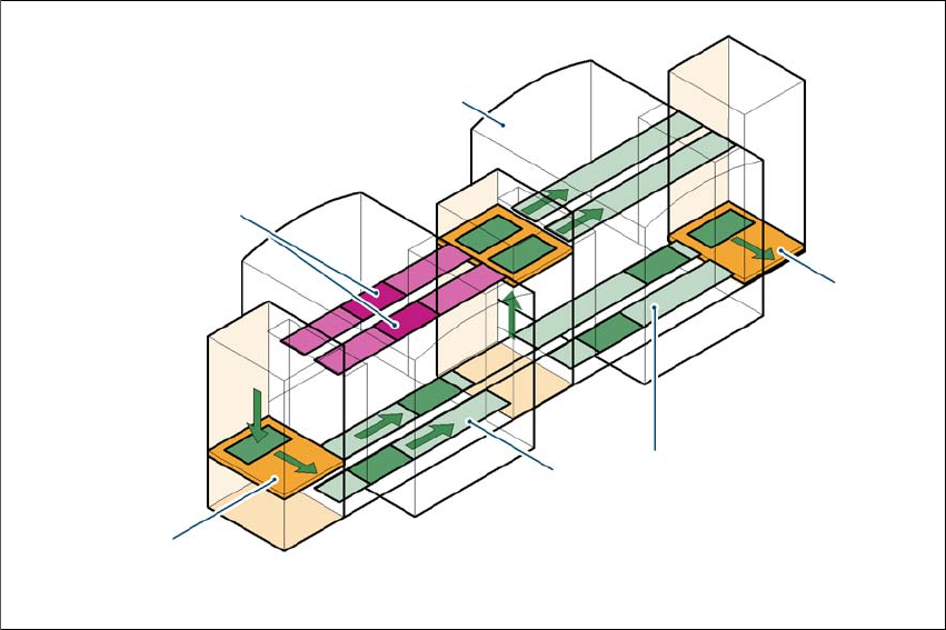
Horizontal/vertical lift (horizontal/vertical shuttle) 6
There is an HV shuttle at the start of a line, between the machines and at the end of the line. It
carries the PCBs between the underfloor and processing levels, and between the two tracks on
the underfloor conveyors.
6
Fig. 6.13 - 2 Horizontal / vertical shuttle (HV shuttle), conveyor track change and lift function
Horizontal conveyor
HV shuttle
Lift function
Vertical conveyor
Unplaced
Placed
Standard
conveyor level
Underfloor
conveyor level
HV shuttle
Conveyor track change
6 Station extensions User manual SIPLACE D4
6.13 SIPLACE Productivity Lift From software version SR.605.xx 07/2008 EN Edition
248
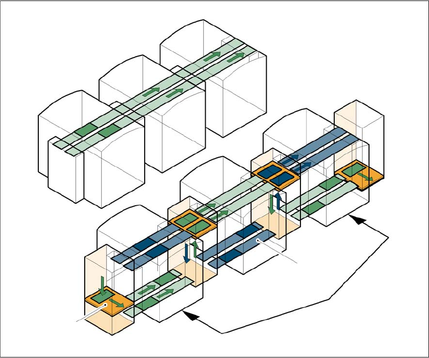
6.13.3 Advantages of the productivity lift
The productivity lift can raise the productivity of a line overall because it increases the placement
rates of the machines on the line.
6
Fig. 6.13 - 3 Productivity lift – Avoiding stoppages
If lines are connected in parallel, individual machines may fail without bringing the entire line to a
standstill. It is also possible access individual machines while the rest of the line continues placing
without interruption.
This could be for
– process-related investigations or test operation
– programming PCB fiducials, package forms or test placements
– maintenance or repairs
– operating errors, such as not splicing tapes on in good time or missing components.
Another advantage is that the line can be reconfigured as required using the software, without
having to reset the machines.
Conveyor section, processing
Placement machine
Horizontal
and vertical lift
Underfloor conveyor
Track change