00195779-0102_UM_D4_SR605_EN.pdf - 第63页
User manual SIPLACE D4 2 Operational safety From software version SR.605.xx 07/2008 EN Edition 2.6 Safety equipment 63 2.6.2.3 Position of control compute r , connecting socket s and buttons for the component trolley 2 F…
2 Operational safety User manual SIPLACE D4
2.6 Safety equipment From software version SR.605.xx 07/2008 EN Edition
62
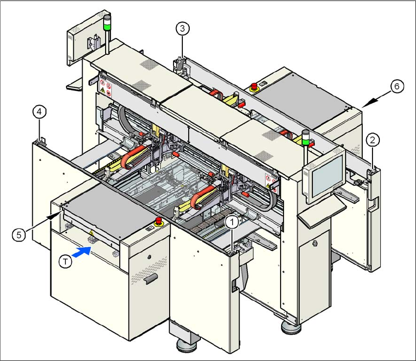
2.6.2.2 Position of protective switches on the machine
2
Fig. 2.6 - 5 Position of protective switches on the machine
2
(1) Protective cover switch, location 1
(2) Protective cover switch, location 2
(3) Protective cover switch, location 3
(4) Protective cover switch, location 4
(5) Protective switch for the cover flap on the PCB conveyor input side
(6) Protective switch for the cover flap on the PCB conveyor output side
(T) PCB transport direction
User manual SIPLACE D4 2 Operational safety
From software version SR.605.xx 07/2008 EN Edition 2.6 Safety equipment
63
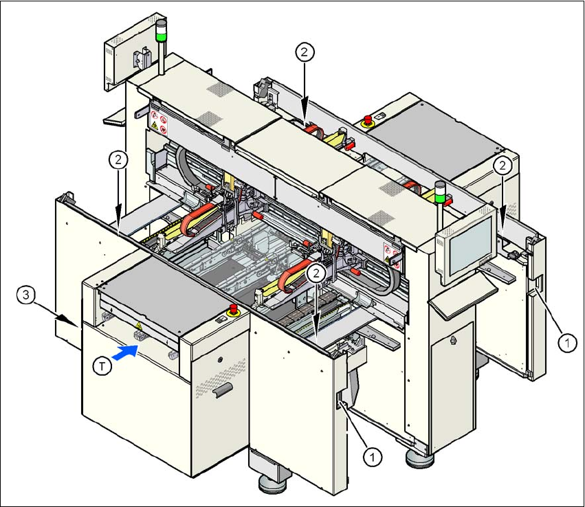
2.6.2.3 Position of control computer, connecting sockets and buttons for the component
trolley
2
Fig. 2.6 - 6 Control computer, connecting sockets and buttons for the component trolley
2
(1) Socket for connecting the component trolley
(2) Push-button for raising the component table, with the hinged cover flap over it
(3) Control computer
(T) PCB transport direction

2 Operational safety User manual SIPLACE D4
2.6 Safety equipment From software version SR.605.xx 07/2008 EN Edition
64
2.6.2.4 Description of the functions
Main power switch in the OFF position (see item 1 in Fig. 2.6 - 3
) 2
The main power switch disconnects the three phases U, V and W from the power supply.
WARNING 2
The following power supply components still carry potentially lethal voltages even if the main
power switch is switched off:
– Infeed terminals X100 (item 3 in Fig. 2.6 - 7
, page 67)
– Discharge reactor Z2 (item 5 in Fig. 2.6 - 7
), fuses FU, FV, FW and FBU (item 2 in Fig. 2.6 - 7)
– Line filter Z1 (item 6 in Fig. 2.6 - 7
)
– Service socket BU1 (item 4 in Fig. 2.6 - 7
)
– Cable connection terminals 1, 3, and 5 of the S1 main power switch (item 7 in Fig. 2.6 - 7
)
– The color of all individual wires, which still carry potentially lethal voltages even if the main
power switch is switched off, is brown.
→ Death, serious injury or considerable damage may result if these machines are handled in-
correctly.
→ Always follow the applicable accident prevention and DIN regulations (particularly DIN
EN 60 204, part 1) and the applicable regulations in your own country.
→ The safety door to the power supply must ONLY be opened by appropriately qualified and
trained personnel.
Main power switch in the ON position 2
After switching on the main power switch, the control computer and the machine controller will
start. All supply voltages, apart from the link voltages for the gantry axes (200 V) and the star axes
(150 V) are then available.
Stop button, black (items 2 and 7 in Fig. 2.6 - 3 and items 3 and 5 in Fig. 2.6 - 4) 2
These buttons are used to stop the machine.
Start button, white (items 3 and 6 in Fig. 2.6 - 3 and items 2 and 4 in Fig. 2.6 - 4) 2
After switching on the main power switch you will be prompted to press the start button in order to
start the machine for placement jobs. The same prompt appears if you open the protective covers
or the press the EMERGENCY-STOP button.