00195779-0102_UM_D4_SR605_EN.pdf - 第74页
2 Operational safety User manual SIPLACE D4 2.7 Residual voltages and discharge times in the machin e From software version SR.605.xx 07/2008 EN Edition 74 Fig. 2.7 - 2 Measuring points on the power supply unit 2 2.7.1 O…
User manual SIPLACE D4 2 Operational safety
From software version SR.605.xx 07/2008 EN Edition 2.7 Residual voltages and discharge times in the machine
73
2.7 Residual voltages and discharge times in the
machine
If the EMERGENCY STOP button is pressed or the machine is switched off, the 200 VDC link volt-
age for the gantry axes and the 150 VDC link voltage for the star axes are reduced to harmless
residual voltages in a very short time.
WARNING 2
The machine is supplied with 3 x 200 VAC, 3 x 208 VAC, 3 x 230 VAC, 3 x 380 VAC,
3 x 400 VAC or 3 x 415 VAC ± 5 %, 50/60 Hz main power voltage. This means that some parts of
the system carry potentially lethal voltages - even when switched off at the main power switch.
Incorrect handling of the machine can therefore result in death or severe injury or considerable
damage to equipment.
→ Always follow the applicable accident prevention and DIN regulations (particularly DIN EN 60
204, part 1).
→ The guards over the power supply unit and the axis unit must ONLY be opened by appropri-
ately qualified and trained personnel.
2
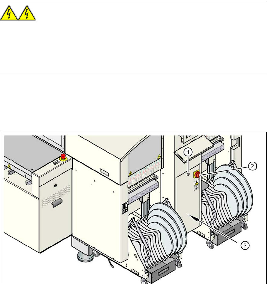
Fig. 2.7 - 1 Power supply unit
(1) Padlock with bolt in the cover
(2) Main power switch
(3) Power supply unit behind the cover
2 Operational safety User manual SIPLACE D4
2.7 Residual voltages and discharge times in the machine From software version SR.605.xx 07/2008 EN Edition
74
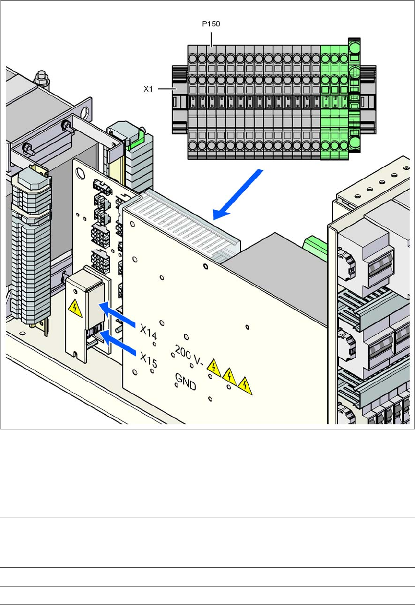
Fig. 2.7 - 2 Measuring points on the power supply unit
2
2.7.1 Operating voltages, residual voltages and discharge times after pressing
the emergency stop button
2
Pin X14 and terminal P150 (X1)
measured to X15 (GND)
Voltage in
normal mode
Residual voltage
after EMERG.
STOP
Discharge
times
X14 + 200 VDC < 60 VDC 4 s
P150 (X1) + 150 VDC < 60 VDC 1 s
User manual SIPLACE D4 2 Operational safety
From software version SR.605.xx 07/2008 EN Edition 2.8 Disabling the compressed air supply and discharging the pressure
75
2.7.2 Residual voltages and discharge times after switching off at the main switch
2
2
CAUTION 2
To avoid losing data, assess the following criteria before switching off your machine (apart from in
emergencies):
– Has the machine finished transmitting machine, setup and panel data?
– Has the machine finished processing the PCB?
– Has the machine completed the run-up phase?
2.8 Disabling the compressed air supply and discharg-
ing the pressure
The compressed air working pressure of the machine is set to 0.51 ± 0.01 MPa (5.1 ± 0.1 bar).
The position of the compressed air unit is indicated by Fig. 2.8 - 1
. The compressed air supply to
the machine can be interrupted using the shutoff valve (item 1 in Fig. 2.8 - 1
).
→ Use the machine key to release the cover lock.
→ Lift off the cover (see Fig. 2.8 - 1
).
→ Turn the lever on the shutoff valve (item 1 in Fig. 2.8 - 1
) from the vertical to the horizontal
position.
→ Watch the working pressure gauge (item 4 in Fig. 2.8 - 1
). When the machine is switched on,
the pressure discharges to 0 MPa (0 bar) within 1 minute.
CAUTION
When the machine is switched on, do not use the stop valve to interrupt the compressed air sup-
ply for more than 30 minutes. If you need to shut off the pneumatic system for longer in order to
carry out preventive maintenance or servicing work, you must switch the machine off at the main
switch and disconnect it from the power supply.
Pin X14 and terminal P150 (X1)
measured to X15 (GND)
Residual voltages when
main power switch is off Discharge times
X14 < 60 VDC < 4 s
P150 (X1) < 60 VDC < 1 s