3MAINTENANCE__O.pdf - 第105页
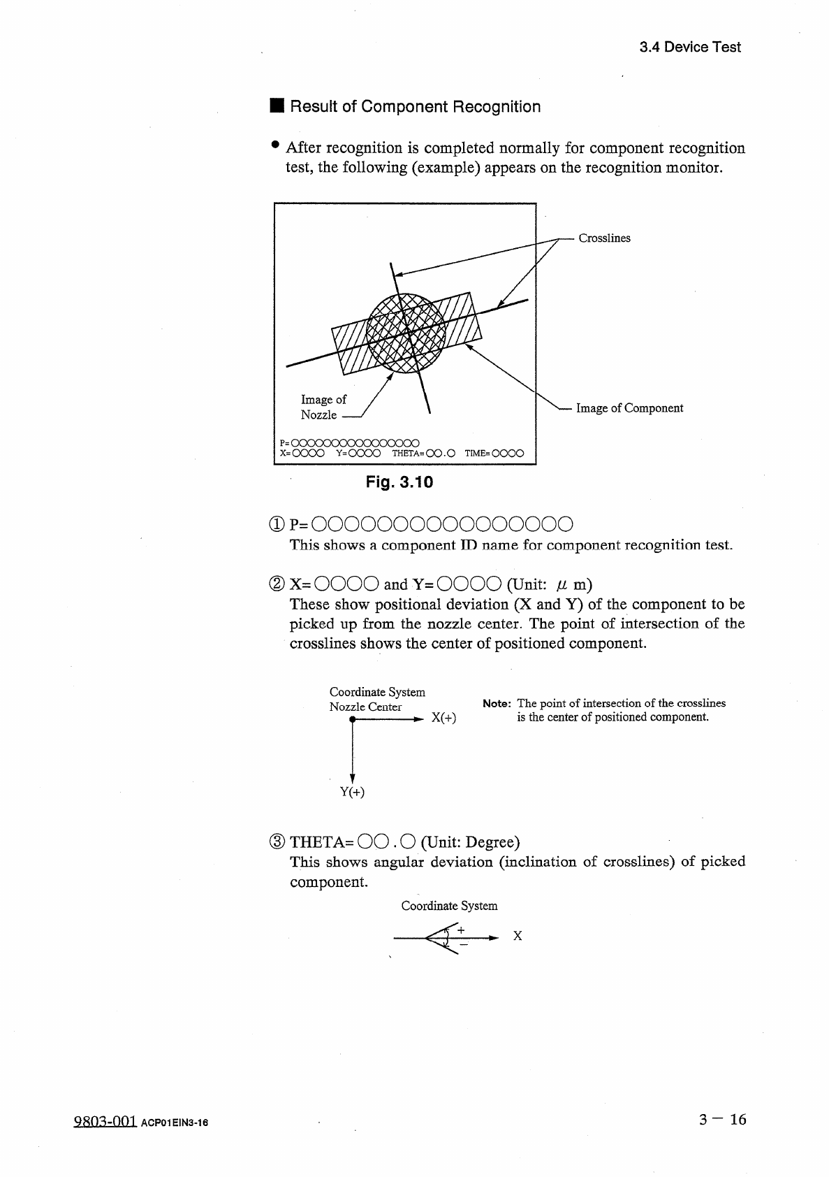
3.4 Device Test ■ Result of Component Recognition • After recognition is completed normally for component recognition test , the following ( example ) appears on the recognition monitor . : oooooooooooooooo = 0000 Y ^ OO…
3.4
Device
Test
⑥
When
the
[
FORWARD
]
or
[
REVERSE
]
key
located
under
the
label
“
NOZZLE
ROTATE
N
1
JOG
”
is
selected
and
the
[
MOVE
]
button
is
pressed
,
angle
of
the
component
can
be
jogged
.
(
6
)
Test
ID
data
can
be
edited
before
or
after
a
recognition
test
is
performed
.
•
When
the
recognition
test
results
in
“
NG
”
(
No
Good
)
,
change
the
test
ID
data
and
re
-
perform
the
recognition
test
.
(
7
)
When
the
[
HYSTERESIS
TEST
]
key
is
pressed
,
the
“
HYSTERESIS
TEST
”
display
appears
on
the
screen
.
Hysteresis
test
operation
is
possible
only
when
a
component
is
located
at
the
recognition
station
after
the
operation
menus
of
the
“
COMPONENT
RECOG
.
TEST
”
display
(
Fig
.
3.8
)
implemented
.
•
A
hysteresis
test
is
performed
according
to
the
parameters
set
in
the
text
boxes
of
the
labels
“
OVERALL
TACT
-
TIME
OVERALL
TACT
-
TIME
are
REDUCTION
MODE
”
and
REDUCTION
TACT
-
TIME
”
,
the
parameter
set
in
the
text
box
of
the
label
“
HEAD
ROTATE
THETA
”
,
the
parameter
set
in
the
text
box
of
the
label
“
#
OF
HYSTERESIS
”
,
and
the
parameter
set
in
the
text
box
of
the
label
“
PLACEMENT
MODE
”
.
After
that
,
the
test
result
is
displayed
.
(
8
)
To
Exit
from
Component
Recognition
Test
Session
•
Select
the
[
ZEROING
FDR
.
AXIS
&
COMP
.
COLLECTION
]
key
and
press
the
[
MOVE
]
button
.
The
feeder
axis
,
the
X
/
Y
table
,
and
the
X
/
Y
return
to
their
origins
and
the
component
located
at
the
recognition
station
is
transferred
to
No
.
8
station
(
the
station
just
before
the
machine
takes
placement
action
)
.
•
Collect
the
component
.
camera
Note
:
When
the
[
VAC
.
VALVE
ON
/
OFF
]
switch
is
pressed
,
the
vacuum
for
vacuum
nozzles
can
be
turned
ON
or
OFF
.
3
—
15
9803
-
001
ACP
01
EIN
3
-
15
3.4
Device
Test
■
Result
of
Component
Recognition
•
After
recognition
is
completed
normally
for
component
recognition
test
,
the
following
(
example
)
appears
on
the
recognition
monitor
.
:
oooooooooooooooo
=
0000
Y
^
OOOO
THETA
-
OO
.
O
TIME
=
QOOO
Fig
.
3.10
①
p
=
0000000000000000
This
shows
a
component
ID
name
for
component
recognition
test
.
②
X
=
OOOO
and
Y
=
OOOO
(
Unit
:
/
/
m
)
These
show
positional
deviation
(
X
and
Y
)
of
the
component
to
be
picked
up
from
the
nozzle
center
.
The
point
of
intersection
of
the
crosslines
shows
the
center
of
positioned
component
.
Coordinate
System
Nozzle
Center
Note
:
The
point
of
intersection
of
the
crosslines
is
the
center
of
positioned
component
.
③
THETA
=
00.0
(
Unit
:
Degree
)
This
shows
angular
deviation
(
inclination
of
crosslines
)
of
picked
component
.
Coordinate
System
X
3
-
16
9803
-
001
ACP
01
E
1
N
3
-
16
3.4
Device
Test
④
TIME
(
Unit
:
1
/
1000
seconds
)
This
shows
processing
time
of
component
recognition
.
“
0
”
(
zero
)
is
displayed
when
the
processing
time
is
fast
enough
to
keep
up
with
the
highest
placement
speed
.
Use
the
value
as
reference
to
be
set
in
the
text
box
of
the
label
“
RECOG
.
TIME
”
at
the
“
COMPONENT
LIBRARY
”
display
.
•
When
an
error
in
recognition
occurs
during
component
recognition
test
,
nothing
appears
on
the
recognition
monitor
and
an
error
message
(
recognition
error
)
is
issued
on
the
touch
screen
.
3
一
17
9803
-
001
ACP
01
EIN
3
-
17