3MAINTENANCE__O.pdf - 第112页
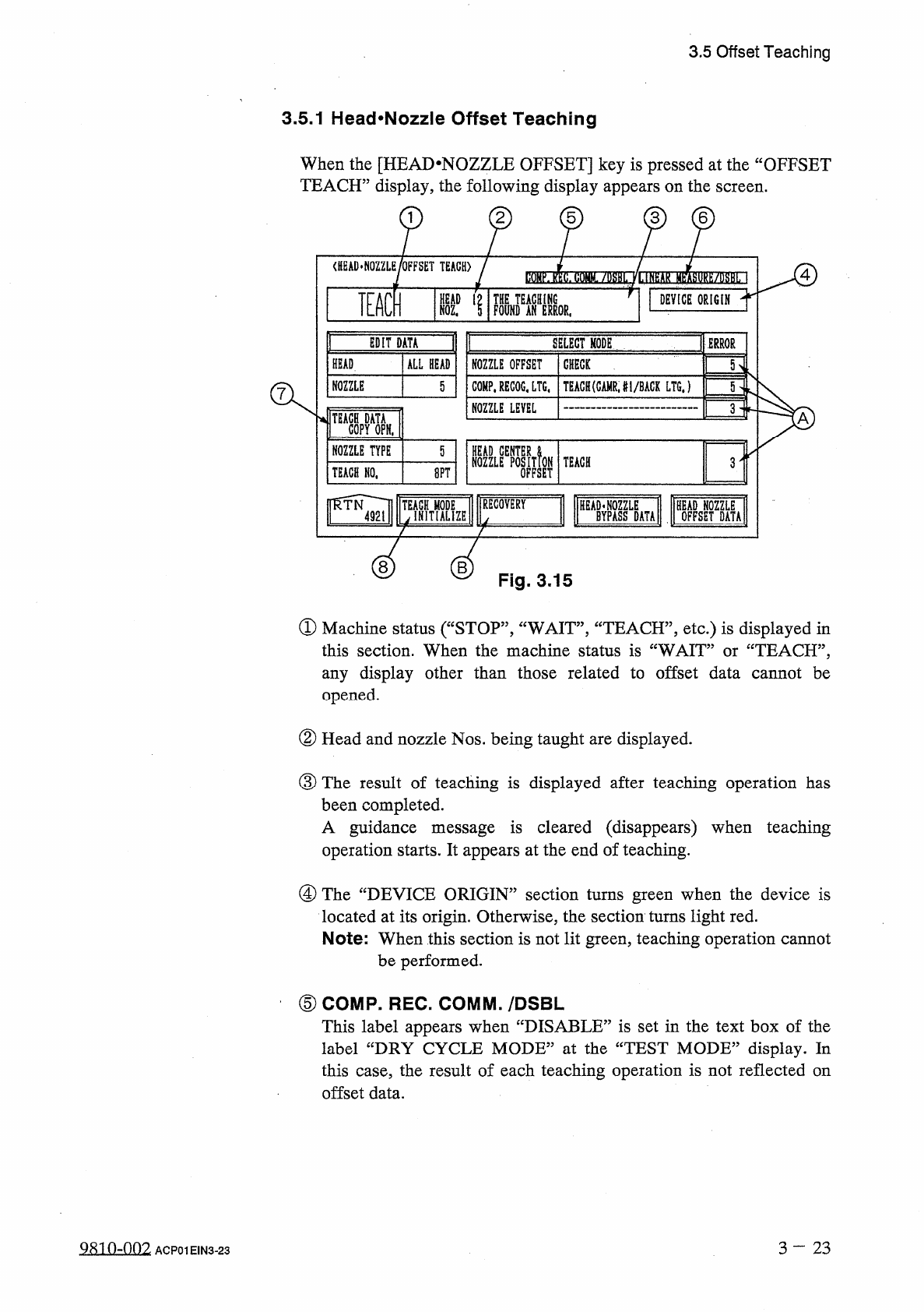
3.5 Offset Teaching 3.5 . 1 Head ^ Nozzle Offset Teaching When the [ HEAD - NOZZLE OFFSET ] key is pressed at the “ OFFSET TEACH ” display , the following display appears on the screen . 2 5 < HEAD * NOZZLE / OFFSET T…
3.5
Offset
Teaching
Set
the
[
OPERATION
/
SET
UP
]
switch
to
the
“
SET
UP
”
side
before
performing
the
above
-
related
maintenance
work
(
including
jig
attachment
)
.
Only
the
person
in
charge
of
maintenance
work
should
perform
teaching
operations
.
Teaching
operations
cannot
be
performed
with
the
[
OPERATION
/
SET
UP
]
switch
set
to
the
“
SET
UP
”
side
.
A
WARNING
3
-
2 2
9803
-
001
ACP
01
EIN
3
-
22
3.5
Offset
Teaching
3.5
.
1
Head
^
Nozzle
Offset
Teaching
When
the
[
HEAD
-
NOZZLE
OFFSET
]
key
is
pressed
at
the
“
OFFSET
TEACH
”
display
,
the
following
display
appears
on
the
screen
.
2
5
<
HEAD
*
NOZZLE
/
OFFSET
TEACH
)
4
TEACH
S
'
1
DEVICE
ORIGIN
TERROR
EDIT
DATA
SELECT
MODE
HEAD
ALL
HEAD
ROZZLE
OFFSET
GttEGK
NOZZLE
TEACH
(
GAMRJ
1
/
BACK
LTGJ
5
COMP
.
RECOG
,
LTG
,
5
NOZZLE
LEVEL
3
A
NOZZLE
TYPE
5
NOZZLEEPOSITfoN
OFFSET
TEACH
3
TEACH
NO
,
8
PT
[
RECOVERY
«
ZE
B
Fig
.
3.15
①
Machine
status
(
“
STOP
”
,
“
WAIT
”
,
“
TEACH
”
,
etc
.
)
is
displayed
in
:
TEACH
,
,
,
this
section
.
When
the
machine
status
is
“
WAIT
any
display
other
than
those
related
to
offset
data
cannot
be
opened
.
or
②
Head
and
nozzle
Nos
.
being
taught
are
displayed
.
③
The
result
of
teaching
is
displayed
after
teaching
operation
has
been
completed
.
A
guidance
message
is
cleared
(
disappears
)
when
teaching
operation
starts
.
It
appears
at
the
end
of
teaching
.
@
The
“
DEVICE
ORIGIN
”
section
turns
green
when
the
device
is
located
at
its
origin
.
Otherwise
,
the
section
turns
light
red
.
Note
:
When
this
section
is
not
lit
green
,
teaching
operation
cannot
be
performed
.
⑤
COMP
.
REC
.
COMM
.
/
DSBL
This
label
appears
when
“
DISABLE
”
is
set
in
the
text
box
of
the
label
“
DRY
CYCLE
MODE
”
at
the
“
TEST
MODE
”
display
.
In
this
case
,
the
result
of
each
teaching
operation
is
not
reflected
on
offset
data
.
3
—
23
Q
8
in
-
002
ACP
01
EIN
3
-
23
3.5
Offset
Teaching
⑥
LINEAR
MEASURE
/
DSBL
This
label
appears
when
“
DISABLE
”
is
set
in
the
text
box
of
the
label
“
LINEAR
MEASURE
MODE
”
at
the
“
TEST
MODE
”
display
.
In
this
case
,
the
result
of
each
teaching
operation
is
not
reflected
on
offset
data
.
®
When
the
[
TEACH
DATA
COPY
OPN
.
]
key
is
pressed
,
the
head
center
offset
is
copied
to
the
head
center
(
B
)
offset
.
(
Refer
to
“
PLACE
.
POS
.
ADJ
.
MODE
”
in
“
4.11
Setting
of
Automatic
Offset
Teaching
Mode
”
in
the
instruction
manual
(
Section
I
:
Operation
Manual
)
for
details
.
)
⑧
[
TEACH
MODE
INITIALIZE
]
Key
When
this
key
is
pressed
,
the
parameters
set
in
“
EDIT
DATA
”
and
“
SELECT
MODE
”
are
initialized
.
(
The
parameters
can
also
be
initialized
at
the
“
AUTO
OFFSET
TEACH
MODE
”
display
.
)
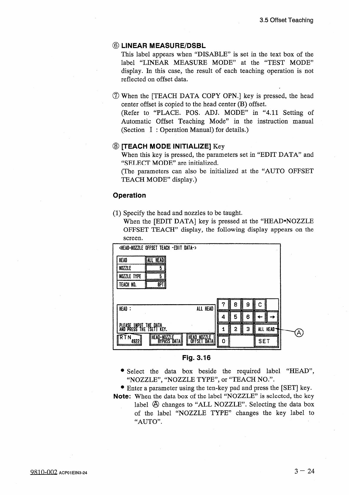
Operation
(
1
)
Specify
the
head
and
nozzles
to
be
taught
.
When
the
[
EDIT
DATA
]
key
is
pressed
at
the
“
HEAD
.
NOZZLE
OFFSET
TEACH
”
display
,
the
following
display
appears
on
the
screen
.
<
HEAD
-
H
02
ZLE
OFFSET
TEACH
-
EDIT
DATA
-
〉
inn
HEAD
T
\
NOZZLE
NOZZLE
TYPE
5
画
TEACH
HO
.
7
8
9
C
ALL
HEAD
HEAD
:
4
5
6
2
3
ALL
HEAD
®
FTN
』
Risllglll
0
SET
Fig
.
3.16
•
Select
the
data
box
beside
the
required
label
“
HEAD
”
,
“
NOZZLE
”
,
“
NOZZLE
TYPE
,,
,
or
“
TEACH
NO
.
,
,
.
•
Enter
a
parameter
using
the
ten
-
key
pad
and
press
the
[
SET
]
key
.
Note
:
When
the
data
box
of
the
label
“
NOZZLE
”
is
selected
,
the
key
label
@
changes
to
of
the
label
“
NOZZLE
TYPE
”
changes
the
key
label
to
“
AUTO
”
.
Selecting
the
data
box
CALL
NOZZLE
”
.
3
~
2 4
9810
-
002
ACP
01
EIN
3
-
24