3MAINTENANCE__O.pdf - 第118页
i 9.999 f 9.999 〈 NOZZLE POSITiOM OFFSET ) 01 / 02 HOZZLE R ( Him ) NOZZLE R ( mra ) NOZZLE 8 ( ID ) NOZZLE R ( IDUJ ) 1 - 1 t o i i i M M - 1 to . 999 7 - 1 fO . 999 10.99 3 iO . 999 5 - 3 10.99 i Mil hrf 7 - \ t i : 9 …
3.5
Offset
Teaching
S
IEYEI
>
L
1
GHTIH
6
.
〈
INDIVIDUAL
NOZZLE
GAIN
01
/
08
BACK
NOZZLE
GAIN
LEVEL
GAIN
LEVEL
GAIN
LEVEL
£
A
1
N
LEVEL
III
礙
III
礙
<
N
0
ZZIE
OFFSET
LOV
MAGNIFICATION
)
01
/
03
NOZZLE
X
(
Hffl
)
Y
m
)
NOZZLE
X
[
ml
.
Y
t
HOZZLE
x
(
nun
)
Y
(
HU
)
(
NOZZLE
OFFSET
HIGH
MAGNIFICATION
)
fli
/
03
NQZZIE
X
(
卿
)
Y
[
咖
1
X
M
Y
(
iB
)
Y
(
咖
}
NOZZLE
HOZZLE
X
(
RID
)
QQQ
QO
aqi
t
0.99
*
5
n
ill
t
ti
:
v
-
Fig
.
3.20
ml
nA
15
:
§
99
iS
:
9
»
QQQ
II
:
1
19
!
\
U
«
:
!
!
n
.
\
m
十
i
tS
:
3
i
9
J
Fig
.
3.19
-
2
Fig
.
3.19
-
1
<
H
0
ZZLE
LEYEL
(
H
)
OFFSET
〉
01
/
02
L
W
NOL
L
(
咖
)
胍
•
l
(
咖
)
NOZ
.
L
(
II
)
NQZ
.
Fig
.
3.21
-
2
MI
tm
i
:
\
IHS
i
:
\
m
<
N
0
ZZL
£
LEYEL
(
L
)
OFFSET
)
01
/
02
AL
(
iB
)
△
L
(
咖
}
H
02
.
NOZ
.
ALW
KOZ
.
△
U
咖
)
.
NOZ
.
mi
i
-
nii
mi
<
N
0
ZZLE
LEVEL
(
L
)
OFFSET
)
01
/
02
L
(
inn
)
L
M
NOZ
.
HOZ
.
MOL
L
W
l
M
)
NOZ
.
t
•
t
.
n
\
-
m
•
i
i
m
十
i
i
il
if
3
-
5
iOi
-
5
19
7
-
5
i
:
n
i
0
:
9
i
51
«
:
53
Fig
.
3.21
-
1
MASTER
手
0
,
99
SCREENS
Fig
.
3.21
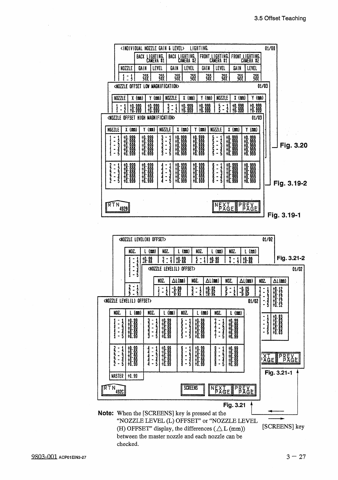
Note
:
When
the
[
SCREENS
]
key
is
pressed
at
the
—
“
NOZZLE
LEVEL
(
L
)
OFFSET
”
or
“
NOZZLE
LEVEL
(
H
)
OFFSET
’
display
,
the
differences
(
AL
(
mm
))
between
the
master
nozzle
and
each
nozzle
can
be
checked
.
[
SCREENS
]
key
QRn
^
-
nm
3
一
27
ACP
01
EIN
3
-
27
i
9.999
f
9.999
〈
NOZZLE
POSITiOM
OFFSET
)
01
/
02
HOZZLE
R
(
Him
)
NOZZLE
R
(
mra
)
NOZZLE
8
(
ID
)
NOZZLE
R
(
IDUJ
)
1
-
1
toiii
MM
-
1
to
.
999
7
-
1
fO
.
999
10.99
3
iO
.
999
5
-
3
10.99
i
Mil
hrf
7
-
\
ti
:
99
9
M M
3.5
Offset
Teaching
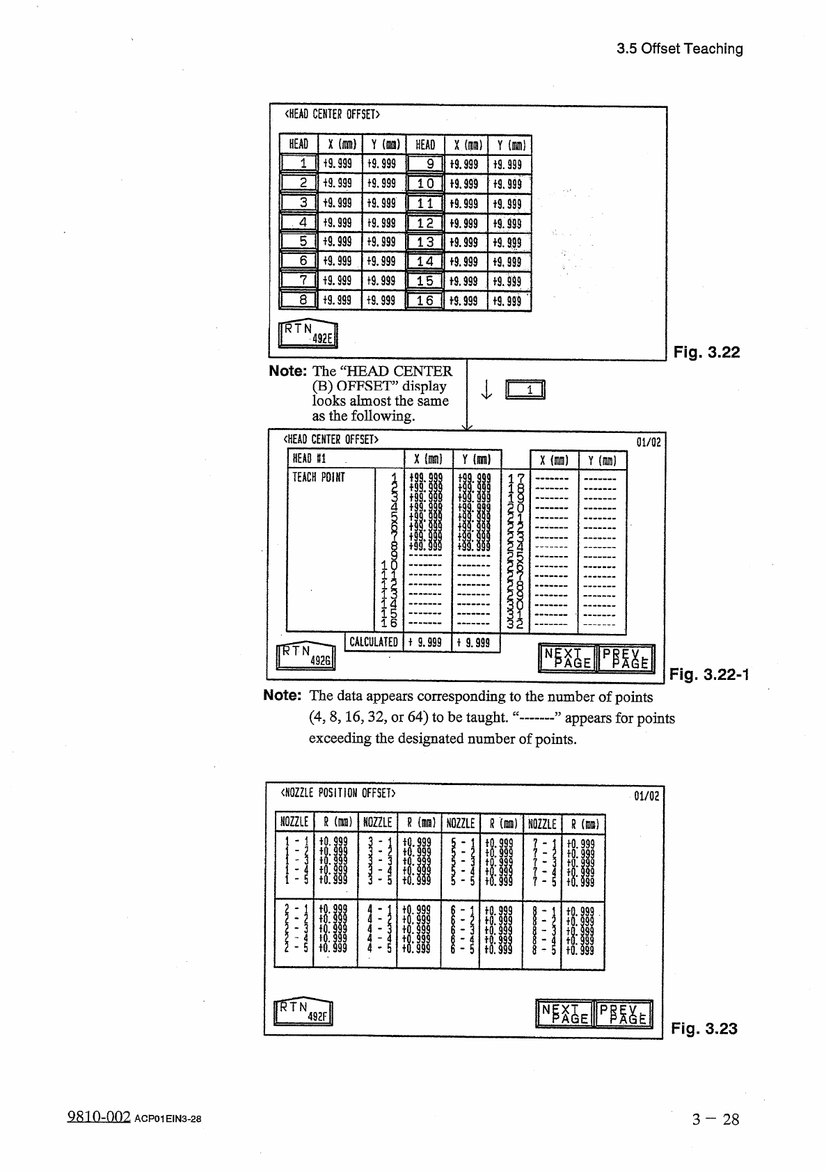
Fig
.
3.22
Note
:
The
“
HEAD
CENTER
(
B
)
OFFSET
”
display
I
looks
almost
the
same
as
the
following
.
〈
HEAD
CENTER
OFFSET
〉
HEAD
81
.
"
TEACH
POINT
01
/
02
x
(
nun
)
Y
(
nun
)
l
?
1
o
I
I
1
16
CALCULATED
MM
Fig
.
3.22
-
1
Note
:
The
data
appears
corresponding
to
the
number
of
points
(
4
,
8
,
16
,
32
,
or
64
)
to
be
taught
,
exceeding
the
designated
number
of
points
.
appears
for
points
Fig
.
3.23
3
-
2 8
QR
10
-
002
ACP
01
EIN
3
-
28
1
〈
HEAD
CENTER
OFFSET
〉
Y
(
is
)
X
(
nan
)
X
(
m
)
Y
(
oil
HEAD
HEAD
+
9.999
9
+
9
.
§
99
«
.
999
19.999
1
tS
.
999
10
19.999
19.999
2
i
9.999
«
.
999
+
9.999
t
9
.
S
9
?
3
4
19.999
f
9.999
19.999
f
9.999
+
9.999
5
+
9.999
f
9.999
a
999
19.999
设
999
6
19.999
a
999
19.999
f
9.999
15
f
9.999
7
tS
.
999
8
f
9.999
+
9.999
1
6
f
9.999
I
^
Wl
na
_
)
QXMWQW
-
w
AMXMXy
-
^
QWQW
9
-
X
QM
999
QXUW
99
In
QVAMXyxMXU
^
+
0
.
+
0
:
說
to
.
-
I
•
'
-
3508
ai
9
ldd
9999
IQ
.
fo
:
fo
.
io
:
R
CWCVGWQWCV
oao
>
Q
>
o
>
c
*
2
N
T
V
H
11
I
1
-
-
T
to
.
io
:
^
^
1
TTU
34
C
3
.
1.1
.
3.5
Offset
Teaching
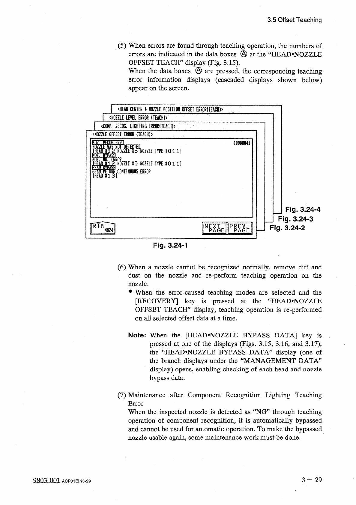
(
5
)
When
errors
are
found
through
teaching
operation
,
the
numbers
of
errors
are
indicated
in
the
data
boxes
@
at
the
“
HEAD
.
NOZZLE
OFFSET
TEACH
”
display
(
Fig
.
3.15
)
.
When
the
data
boxes
@
are
pressed
,
the
corresponding
teaching
error
information
displays
(
cascaded
displays
shown
below
)
appear
on
the
screen
.
<
HEAD
CENTER
l
NOZZLE
POSITION
OFFSET
ERR
0
RnEACH
)
>
〈
NOZZLE
LEVEL
ERROR
(
IEACH
)
>
1
<
C
隱
.
HECDS
.
LiGHTI
肪
ERMR
(
TEACH
)
>
<
N
0
ZZLE
OFFSET
ERROR
{
TEACH
)
>
10000841
m
.
«
DHOZZLE
1
TYPE
80111
CONTINUOUS
ERROR
I
15
NOZZLE
TYPE
8011
]
I
1
HEM
#
13
]
J
Fig
.
3.24
-
4
_
Fig
.
3.24
-
3
Fig
.
3.24
-
2
N
Fig
.
3.24
-
1
(
6
)
When
a
nozzle
cannot
be
recognized
normally
,
remove
dirt
and
dust
on
the
nozzle
and
re
-
perform
teaching
operation
on
the
nozzle
.
•
When
the
error
-
caused
teaching
modes
are
selected
and
the
[
RECOVERY
]
key
is
pressed
at
the
“
HEAD
.
NOZZLE
OFFSET
TEACH
”
display
,
teaching
operation
is
re
-
performed
on
all
selected
offset
data
at
a
time
.
Note
:
When
the
[
HEAD
^
NOZZLE
BYPASS
DATA
]
key
is
pressed
at
one
of
the
displays
(
Figs
.
3.15
,
3.16
,
and
3.17
)
,
the
“
HEAD
.
NOZZLE
BYPASS
DATA
”
display
(
one
of
the
branch
displays
under
the
display
)
opens
,
enabling
checking
of
each
head
and
nozzle
bypass
data
.
MANAGEMENT
DATA
5
(
7
)
Maintenance
after
Component
Recognition
Lighting
Teaching
Error
When
the
inspected
nozzle
is
detected
as
“
NG
”
through
teaching
operation
of
component
recognition
,
it
is
automatically
bypassed
and
cannot
be
used
for
automatic
operation
.
To
make
the
bypassed
nozzle
usable
again
,
some
maintenance
work
must
be
done
.
3
-
29
S
8
Q
3
dQQl
ACP
01
E
1
N
3
-
29