3MAINTENANCE__O.pdf - 第119页
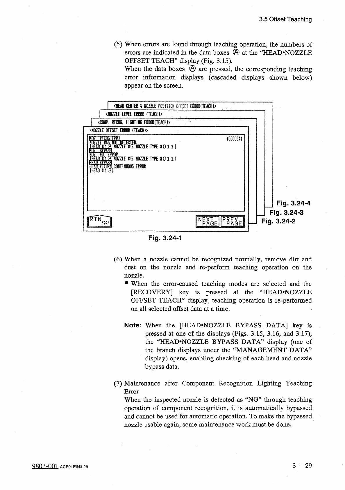
3.5 Offset Teaching ( 5 ) When errors are found through teaching operation , the numbers of errors are indicated in the data boxes @ at the “ HEAD . NOZZLE OFFSET TEACH ” display ( Fig . 3.15 ) . When the data boxes @ ar…
i
9.999
f
9.999
〈
NOZZLE
POSITiOM
OFFSET
)
01
/
02
HOZZLE
R
(
Him
)
NOZZLE
R
(
mra
)
NOZZLE
8
(
ID
)
NOZZLE
R
(
IDUJ
)
1
-
1
toiii
MM
-
1
to
.
999
7
-
1
fO
.
999
10.99
3
iO
.
999
5
-
3
10.99
i
Mil
hrf
7
-
\
ti
:
99
9
M M
3.5
Offset
Teaching
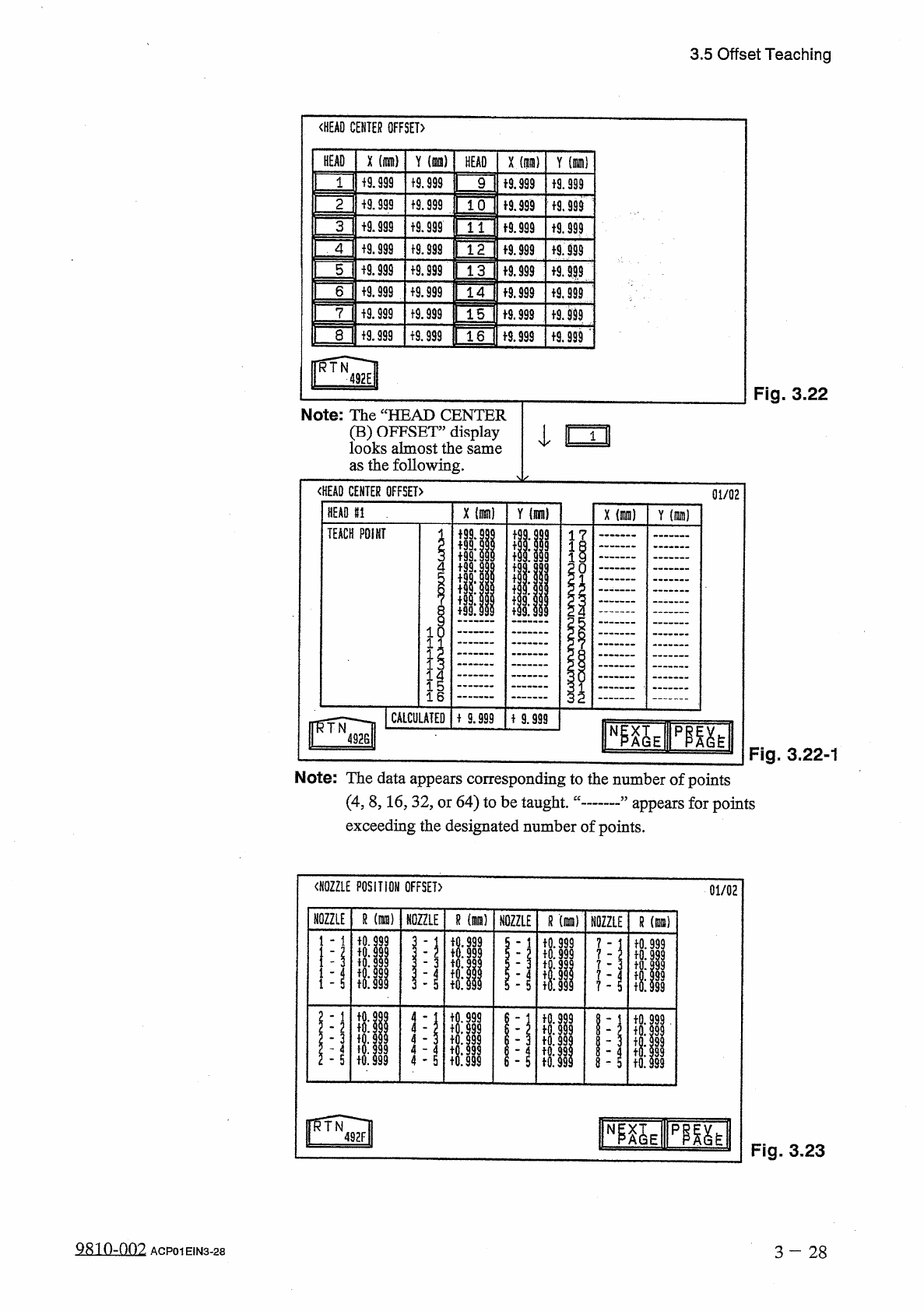
Fig
.
3.22
Note
:
The
“
HEAD
CENTER
(
B
)
OFFSET
”
display
I
looks
almost
the
same
as
the
following
.
〈
HEAD
CENTER
OFFSET
〉
HEAD
81
.
"
TEACH
POINT
01
/
02
x
(
nun
)
Y
(
nun
)
l
?
1
o
I
I
1
16
CALCULATED
MM
Fig
.
3.22
-
1
Note
:
The
data
appears
corresponding
to
the
number
of
points
(
4
,
8
,
16
,
32
,
or
64
)
to
be
taught
,
exceeding
the
designated
number
of
points
.
appears
for
points
Fig
.
3.23
3
-
2 8
QR
10
-
002
ACP
01
EIN
3
-
28
1
〈
HEAD
CENTER
OFFSET
〉
Y
(
is
)
X
(
nan
)
X
(
m
)
Y
(
oil
HEAD
HEAD
+
9.999
9
+
9
.
§
99
«
.
999
19.999
1
tS
.
999
10
19.999
19.999
2
i
9.999
«
.
999
+
9.999
t
9
.
S
9
?
3
4
19.999
f
9.999
19.999
f
9.999
+
9.999
5
+
9.999
f
9.999
a
999
19.999
设
999
6
19.999
a
999
19.999
f
9.999
15
f
9.999
7
tS
.
999
8
f
9.999
+
9.999
1
6
f
9.999
I
^
Wl
na
_
)
QXMWQW
-
w
AMXMXy
-
^
QWQW
9
-
X
QM
999
QXUW
99
In
QVAMXyxMXU
^
+
0
.
+
0
:
說
to
.
-
I
•
'
-
3508
ai
9
ldd
9999
IQ
.
fo
:
fo
.
io
:
R
CWCVGWQWCV
oao
>
Q
>
o
>
c
*
2
N
T
V
H
11
I
1
-
-
T
to
.
io
:
^
^
1
TTU
34
C
3
.
1.1
.
3.5
Offset
Teaching
(
5
)
When
errors
are
found
through
teaching
operation
,
the
numbers
of
errors
are
indicated
in
the
data
boxes
@
at
the
“
HEAD
.
NOZZLE
OFFSET
TEACH
”
display
(
Fig
.
3.15
)
.
When
the
data
boxes
@
are
pressed
,
the
corresponding
teaching
error
information
displays
(
cascaded
displays
shown
below
)
appear
on
the
screen
.
<
HEAD
CENTER
l
NOZZLE
POSITION
OFFSET
ERR
0
RnEACH
)
>
〈
NOZZLE
LEVEL
ERROR
(
IEACH
)
>
1
<
C
隱
.
HECDS
.
LiGHTI
肪
ERMR
(
TEACH
)
>
<
N
0
ZZLE
OFFSET
ERROR
{
TEACH
)
>
10000841
m
.
«
DHOZZLE
1
TYPE
80111
CONTINUOUS
ERROR
I
15
NOZZLE
TYPE
8011
]
I
1
HEM
#
13
]
J
Fig
.
3.24
-
4
_
Fig
.
3.24
-
3
Fig
.
3.24
-
2
N
Fig
.
3.24
-
1
(
6
)
When
a
nozzle
cannot
be
recognized
normally
,
remove
dirt
and
dust
on
the
nozzle
and
re
-
perform
teaching
operation
on
the
nozzle
.
•
When
the
error
-
caused
teaching
modes
are
selected
and
the
[
RECOVERY
]
key
is
pressed
at
the
“
HEAD
.
NOZZLE
OFFSET
TEACH
”
display
,
teaching
operation
is
re
-
performed
on
all
selected
offset
data
at
a
time
.
Note
:
When
the
[
HEAD
^
NOZZLE
BYPASS
DATA
]
key
is
pressed
at
one
of
the
displays
(
Figs
.
3.15
,
3.16
,
and
3.17
)
,
the
“
HEAD
.
NOZZLE
BYPASS
DATA
”
display
(
one
of
the
branch
displays
under
the
display
)
opens
,
enabling
checking
of
each
head
and
nozzle
bypass
data
.
MANAGEMENT
DATA
5
(
7
)
Maintenance
after
Component
Recognition
Lighting
Teaching
Error
When
the
inspected
nozzle
is
detected
as
“
NG
”
through
teaching
operation
of
component
recognition
,
it
is
automatically
bypassed
and
cannot
be
used
for
automatic
operation
.
To
make
the
bypassed
nozzle
usable
again
,
some
maintenance
work
must
be
done
.
3
-
29
S
8
Q
3
dQQl
ACP
01
E
1
N
3
-
29
3.5
Offset
Teaching
•
The
following
explains
about
causes
and
remedies
(
troubleshooting
)
in
order
of
frequency
.
①
Stained
Nozzle
Distinction
:
Lighting
check
results
in
“
NG
”
on
a
specific
nozzle
.
An
NG
factor
may
be
found
visually
in
the
nozzle
image
on
the
recognition
monitor
.
Remedy
:
Wipe
the
nozzle
end
and
the
tapered
area
with
a
soft
cloth
.
②
Stained
Glass
Surface
of
Ring
Lighting
Distinction
:
Lighting
check
results
in
“
NG
”
on
almost
all
heads
and
nozzles
.
Remedy
:
Remove
any
foreign
residues
from
the
glass
surface
and
wipe
the
surface
with
a
soft
dry
cloth
.
③
Stained
Diffusion
Plate
Distinction
:
Lighting
check
results
in
“
NG
”
on
specific
heads
and
nozzles
.
Remedy
:
Wipe
the
diffusion
plate
(
red
acrylic
plate
on
the
lower
surface
of
placement
head
)
with
a
soft
cloth
.
④
Deterioration
of
Lighting
Distinction
:
When
the
level
of
deterioration
is
small
,
light
checking
results
in
“
NG
”
on
a
specific
nozzle
.
When
there
is
considerable
deterioration
,
“
NG
”
is
caused
on
almost
all
heads
and
nozzles
.
Remedy
:
Consult
our
service
personnel
for
re
-
adjustment
of
the
light
source
unit
.
Replace
the
lamp
of
the
light
source
unit
.
Adjust
the
image
input
parameters
.
■
Time
for
Lamp
Replacement
The
lighting
deterioration
rate
of
the
halogen
lamp
which
appears
after
longterm
use
is
10
%
when
power
is
supplied
for
5
,
000
-
6
,
000
hours
(
=
Approx
.
7
8
months
)
.
While
the
lighting
deterioration
rate
is
10
%
-
20
%
(
Approx
.
1
-
year
use
under
normal
condition
)
,
the
lamp
must
be
replaced
with
a
new
one
.
■
Reproducibility
of
Component
Recognition
Lighting
Teaching
Result
The
halogen
lamp
used
for
component
recognition
lighting
normally
shows
the
deterioration
of
lighting
after
longterm
use
.
In
addition
,
some
changes
in
the
light
intensity
are
caused
due
to
ambient
temperature
and
the
time
of
power
supply
.
Therefore
,
a
result
of
lighting
check
sometimes
shows
“
OK
”
or
“
NG
”
depending
upon
the
time
frame
and
/
or
the
room
temperature
when
component
recognition
lighting
teaching
operation
was
performed
and
the
lighting
condition
is
very
similar
to
the
detection
criteria
.
When
maintenance
work
is
done
but
component
recognition
lighting
teaching
operation
still
results
in
“
NG
”
,
there
might
be
a
sizeable
difference
between
the
pre
-
adjustment
at
shipment
and
the
actual
environmental
condition
.
In
this
case
,
consult
our
service
personnel
for
detailed
information
.
9
sn
^
-
nm
ACP
01
EIN
3
-
30