3MAINTENANCE__O.pdf - 第122页
3.5 Offset Teaching 3.5 . 2 Head Origin Offset Teaching When the [ HEAD ORIGIN OFFSET ] key is pressed at the “ OFFSET TEACH ” display , the following display appears on the screen . 2 3 5 〈 HEAD ORIGIN OFFSET TEACH ) OT…
3.5
Offset
Teaching
(
8
)
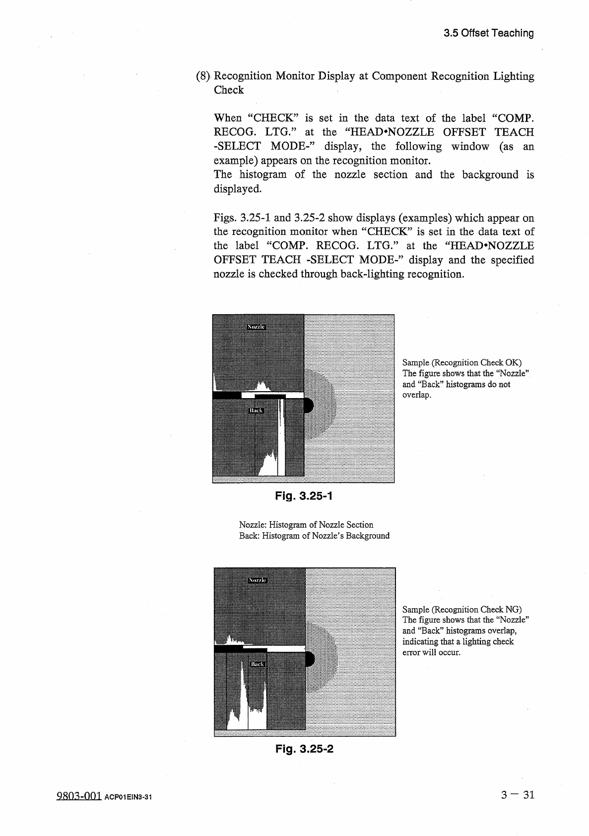
Recognition
Monitor
Display
at
Component
Recognition
Lighting
Check
When
“
CHECK
”
is
set
in
the
data
text
of
the
label
“
COMP
.
RECOG
.
LTG
•
”
at
the
“
HEAD
.
NOZZLE
OFFSET
TEACH
-
SELECT
MODE
-
”
display
,
the
following
window
(
as
an
example
)
appears
on
the
recognition
monitor
.
The
histogram
of
the
nozzle
section
and
the
background
is
displayed
.
Figs
.
3.25
-
1
and
3.25
-
2
show
displays
(
examples
)
which
appear
on
the
recognition
monitor
when
“
CHECK
”
is
set
in
the
data
text
of
the
label
“
COMP
.
RECOG
.
LTG
/
5
at
the
“
HEAD
*
NOZZLE
OFFSET
TEACH
-
SELECT
MODE
-
’
,
display
and
the
specified
nozzle
is
checked
through
back
-
lighting
recognition
.
Sample
(
Recognition
Check
OK
)
The
figure
shows
that
the
“
Nozzle
”
and
“
Back
”
histograms
do
not
overlap
.
Fig
.
3.25
-
1
Nozzle
:
Histogram
of
Nozzle
Section
Back
:
Histogram
of
Nozzle
’
s
Background
Sample
(
Recognition
Check
NG
)
The
figure
shows
that
the
“
Nozzie
”
and
“
Back
”
histograms
overlap
,
indicating
that
a
lighting
check
error
will
occur
.
Fig
.
3.25
-
2
3
—
3 1
QRO
^
-
Om
ACP
01
EIN
3
-
31
3.5
Offset
Teaching
3.5
.
2
Head
Origin
Offset
Teaching
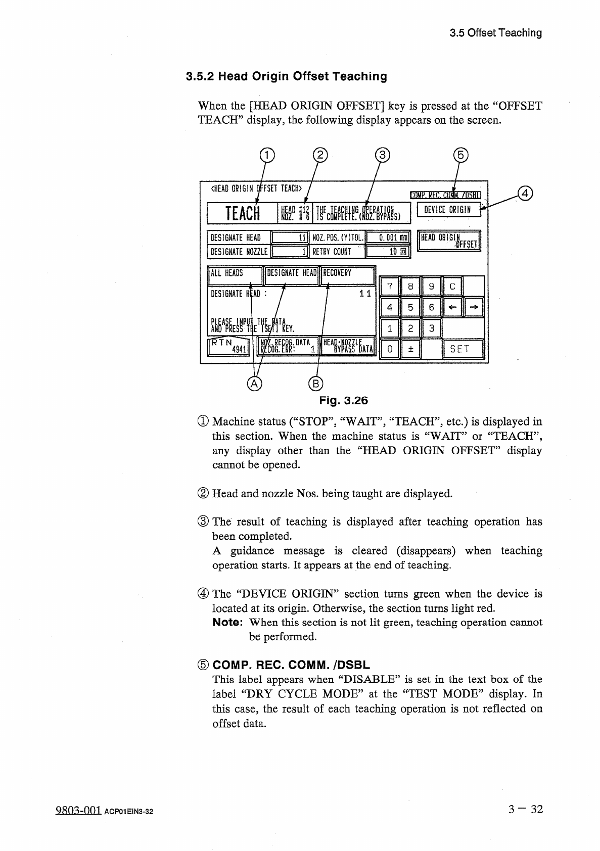
When
the
[
HEAD
ORIGIN
OFFSET
]
key
is
pressed
at
the
“
OFFSET
TEACH
”
display
,
the
following
display
appears
on
the
screen
.
2
3
5
〈
HEAD
ORIGIN
OFFSET
TEACH
)
OTTW
!
!
!
7
IM
0
TEACH
tifl
liE
«
lfs
(
HIs
)
DEVICE
ORIGIN
0
:
001
爾
HEAD
OR
!
B
1
N
0
Z
.
P
0
S
.
(
Y
)
TOL
.
DESIGNATE
HEAD
IFFSET
Wm
3
RETRY
COlif
DESIGNATE
NOZZLE
DESIGNATE
HEAD
RECOVERY
ALL
HEADS
7
8
9
C
DESIGNATE
H
:
AD
:
11
5
6
4
觀
Vf
Y
1
2
3
^
TN
^
Tl
0
SET
4941
±
"
A
Fig
.
3.26
①
Machine
status
(
“
STOP
”
,
“
WAIT
,
,
,
“
TEACH
”
,
etc
.
)
is
displayed
in
this
section
.
When
the
machine
status
is
“
WAIT
”
or
“
TEACH
”
,
any
display
other
than
the
“
HEAD
ORIGIN
OFFSET
”
display
cannot
be
opened
.
②
Head
and
nozzle
Nos
.
being
taught
are
displayed
.
③
The
result
of
teaching
is
displayed
after
teaching
operation
has
been
completed
.
A
guidance
message
is
cleared
(
disappears
)
when
teaching
operation
starts
.
It
appears
at
the
end
of
teaching
.
④
The
“
DEVICE
ORIGIN
”
section
turns
green
when
the
device
is
located
at
its
origin
.
Otherwise
,
the
section
turns
light
red
.
Note
:
When
this
section
is
not
lit
green
,
teaching
operation
cannot
be
performed
.
⑤
COMP
-
REC
.
COMM
.
/
DSBL
This
label
appears
when
“
DISABLE
”
is
set
in
the
text
box
of
the
label
“
DRY
CYCLE
MODE
”
at
the
“
TEST
MODE
”
display
.
In
this
case
,
the
result
of
each
teaching
operation
is
not
reflected
on
offset
data
.
3
~
3 2
ACP
01
EIN
3
-
32
3.5
Offset
Teaching
Operation
(
1
)
Set
parameters
in
the
data
boxes
of
the
labels
“
DESIGNATE
HEAD
”
,
“
DESIGNATE
NOZZLE
”
,
“
NOZ
.
POS
.
(
Y
)
TOL
.
”
,
and
“
RETRY
COUNT
”
.
•
Select
the
data
box
beside
the
required
label
and
enter
parameter
using
the
ten
-
key
pad
.
After
that
,
press
the
[
SET
]
key
.
Press
the
[
ALL
HEADS
]
key
@
to
designate
all
nozzles
for
the
label
“
DESIGNATE
HEAD
”
and
the
[
DESIGNATE
HEAD
]
key
@
to
specify
nozzles
automatically
for
the
label
“
DESIGNATE
NOZZLE
”
.
a
(
2
)
Press
the
[
MOVE
]
button
on
the
operation
panel
to
start
teaching
operation
.
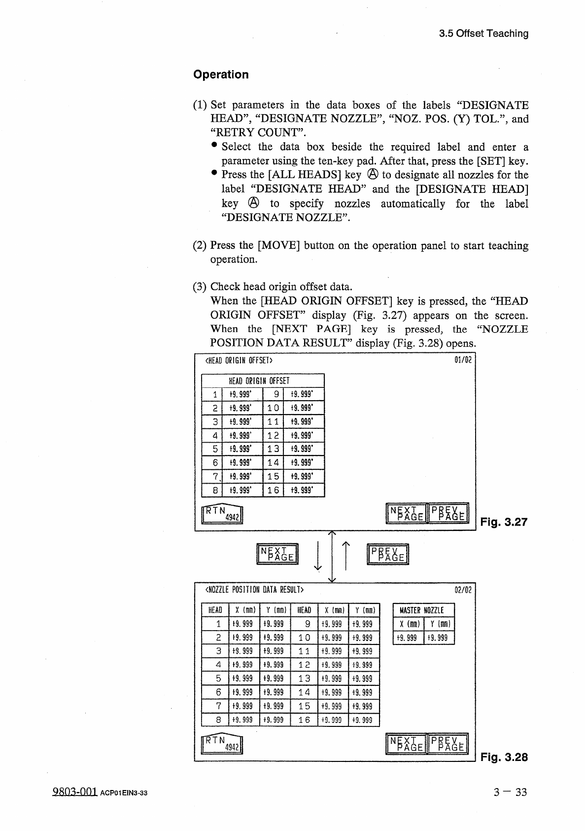
(
3
)
Check
head
origin
offset
data
.
When
the
[
HEAD
ORIGIN
OFFSET
]
key
is
pressed
,
the
“
HEAD
ORIGIN
OFFSET
”
display
(
Fig
.
3.27
)
appears
on
the
When
the
[
NEXT
PAGE
]
key
is
pressed
,
the
“
NOZZLE
POSITION
DATA
RESULT
”
display
(
Fig
.
3.28
)
opens
.
screen
.
01
/
02
〈
HEAD
ORIGIN
OFFSET
)
HEAD
ORIGIN
OFFSET
19
.
999
*
t
9.999
*
9
1
f
9
J
99
.
t
9
J
99
'
1 0
2
十
9.999
*
t
9.999
*
3
1 1
t
9.999
*
1 2
4
t
9.99
S
*
13
t
9.999
*
5
十
9
卿
.
十
9.939
.
14
6
f
9.999
'
f
9.999
*
15
7
t
9.999
.
f
9.999
*
16
8
臨
EIP
隞
EII
N
Fig
.
3.27
〈
NOZZLE
POSITION
DATA
RESULT
〉
02
/
02
X
(
隱
)
HEAD
Y
HEAD
X
[
腦
)
Y
(
mm
)
MASTER
NOZZLE
1
-
9.999
+
9.999
x
(
mra
)
Y
(
m
)
9
+
9.999
f
9.999
M
.
999
2
子
9.999
1 0
19.999
+
9.999
+
9.999
f
9.999
f
8.999
f
9.999
3
1 1
+
9.999
+
9.999
4
f
9.999
+
9.999
12
+
9.999
i
9.999
5
f
9
J
99
i
9.999
13
19.999
+
9.999
6
19.999
十
9.999
14
19.999
进
999
7
f
9
,
999
十
9
,
999
15
+
9.999
+
9.999
19.999
8
+
9.999
16
+
9.999
+
9.999
p
職
^
AGE
N
Fig
.
3.28
Qsn
^
-
nm
3
-
33
ACP
01
EIN
3
-
33