3MAINTENANCE__O.pdf - 第128页
3.5 Offset Teaching 3.5 . 4 P . E . C . Camera Offset Teaching This function automatically calculates offset values X , Y , and Z of the P . E . C . Y , using a special jig P . C . B . and feeds back the calculated value…
3.5
Offset
Teaching
(
6
)
To
exit
from
the
master
head
offset
teaching
session
,
select
the
[
INDEX
THE
TURRET
(
+
)
[
MOVE
]
]
key
and
press
the
[
MOVE
]
button
to
move
the
master
head
to
the
placement
station
.
(
7
)
Detach
the
master
nozzle
and
head
.
(
8
)
When
errors
are
found
through
teaching
operation
,
the
number
of
errors
appears
on
the
[
TEACH
ERR
DATA
#
]
key
.
When
this
key
is
pressed
,
the
following
display
appears
on
the
screen
,
enabling
checking
of
error
contents
.
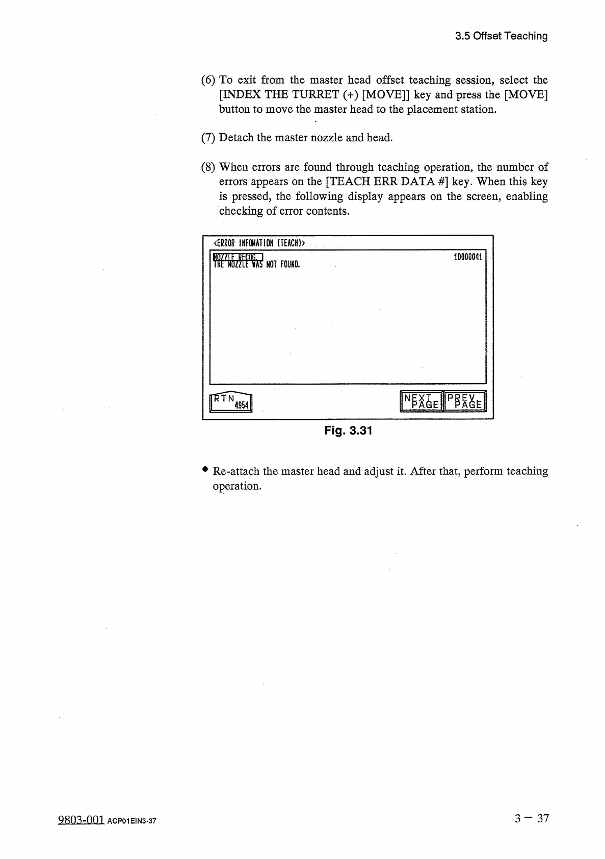
<
ERR
0
R
INFOMATIOH
(
T
£
ACH
)
>
10000041
rayipfiai
Fig
.
3
-
31
•
Re
-
attach
the
master
head
and
adjust
it
.
After
that
,
perform
teaching
operation
.
3
—
37
Q
8
n
^
-
nm
ACP
01
EIN
3
-
37
3.5
Offset
Teaching
3.5
.
4
P
.
E
.
C
.
Camera
Offset
Teaching
This
function
automatically
calculates
offset
values
X
,
Y
,
and
Z
of
the
P
.
E
.
C
.
Y
,
using
a
special
jig
P
.
C
.
B
.
and
feeds
back
the
calculated
values
as
the
offset
data
of
the
P
.
E
.
C
.
camera
.
(
Camera
3
)
and
the
camera
magnification
data
X
and
camera
When
the
[
P
.
E
.
C
.
CAMERA
OFFSET
]
key
is
pressed
at
the
“
OFFSET
TEACH
”
display
,
the
following
display
appears
on
the
screen
.
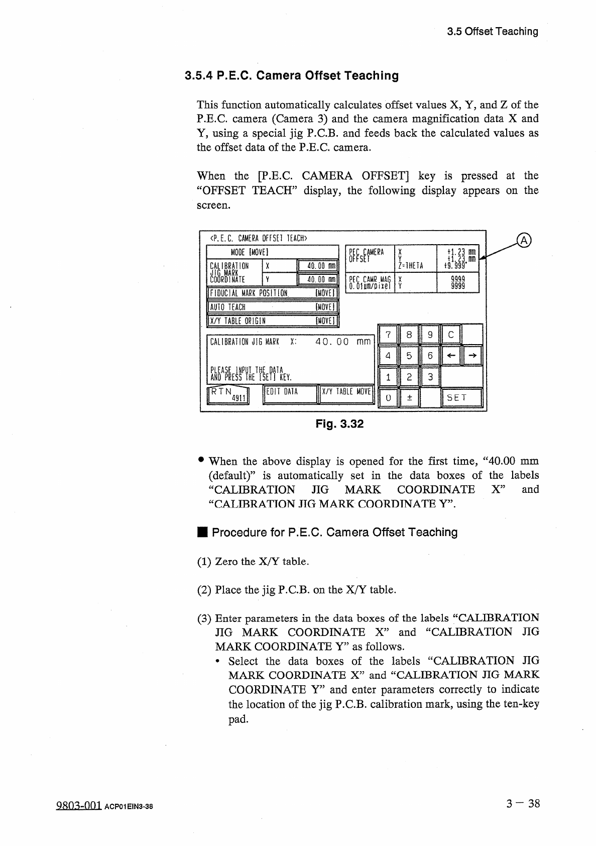
〈
P
.
E
.
C
.
CAMERA
OFFSEI
IEACH
)
MODE
[
MOVE
]
U
.
23
刪
X
Y
CALIBRATION
M
MARK
COORDINATE
40.00
m
Z
=
1
HEIA
X
9999
PEC
CAMR
MAG
.
X
0
.
oium
/
oixei
V
Y
jQJQjrn
9999
I
FIDUCIAL
MARK
PQSlIiON
IOVET
lAUIQ
TEACH
[
tiQVEl
1
X
/
Y
TABLE
QRlGll
mu
\
8
9
C
7
CALIBRATION
JiG
MARK
X
:
40
.
00
mm
5
6
4
ANDAPRESSPIHETfsEIUEV
.
3
2
1
RTN
EDIT
DATA
X
/
Y
TABLE
MOVE
:
SET
0
4911
土
Fig
.
3.32
•
When
the
above
display
is
opened
for
the
first
time
,
“
40.00
mm
(
default
)
”
is
automatically
set
in
the
data
boxes
of
the
labels
“
CALIBRATION
JIG
MARK
COORDINATE
X
”
and
“
CALIBRATION
JIG
MARK
COORDINATE
Y
”
.
■
Procedure
for
P
.
E
.
C
.
Camera
Offset
Teaching
(
1
)
Zero
the
X
/
Y
table
.
(
2
)
Place
the
jig
P
.
C
.
B
.
on
the
X
/
Y
table
.
(
3
)
Enter
parameters
in
the
data
boxes
of
the
labels
“
CALIBRATION
JIG
MARK
COORDINATE
X
”
and
“
CALIBRATION
JIG
MARK
COORDINATE
Y
”
as
follows
.
•
Select
the
data
boxes
of
the
labels
“
CALIBRATION
JIG
MARK
COORDINATE
X
”
and
“
CALIBRATION
JIG
MARK
COORDINATE
Y
”
and
enter
parameters
correctly
to
indicate
the
location
of
the
jig
P
.
C
.
B
.
calibration
mark
,
using
the
ten
-
key
pad
.
3
—
3 8
QRO
^
-
Om
ACP
01
EIN
3
-
38
3.5
Offset
Teaching
(
4
)
Move
the
X
/
Y
table
such
that
the
jig
P
.
C
.
B
.
calibration
mark
enters
the
visual
field
of
the
camera
as
follows
.
•
Select
the
[
FIDUCIAL
MARK
POSITION
[
MOVE
]
]
key
and
press
the
[
MOVE
]
button
.
The
X
/
Y
table
starts
moving
.
•
If
the
calibration
mark
cannot
be
positioned
correctly
in
the
visual
field
of
the
camera
,
open
the
“
X
/
Y
TABLE
MOVE
”
display
and
select
the
[
MANUAL
ALIGNMENT
[
MOVE
]
]
or
the
[
DESIGNATED
POSITION
[
MOVE
]
]
key
,
After
that
,
press
the
[
MOVE
]
button
to
move
the
X
/
Y
table
until
the
calibration
mark
is
correctly
positioned
.
Refer
to
“
[
Operation
of
X
/
Y
Table
Movement
]
”
in
“
3.4
.
2
P
.
E
.
C
.
Recognition
Test
”
for
details
.
(
5
)
Select
the
[
AUTO
TEACH
[
MOVE
]
]
key
and
press
the
[
MOVE
]
button
.
•
Offset
data
is
automatically
taught
through
motion
calibration
operation
.
•
The
parameters
(
saved
values
)
displayed
in
@
are
automatically
updated
to
automatically
calculated
values
.
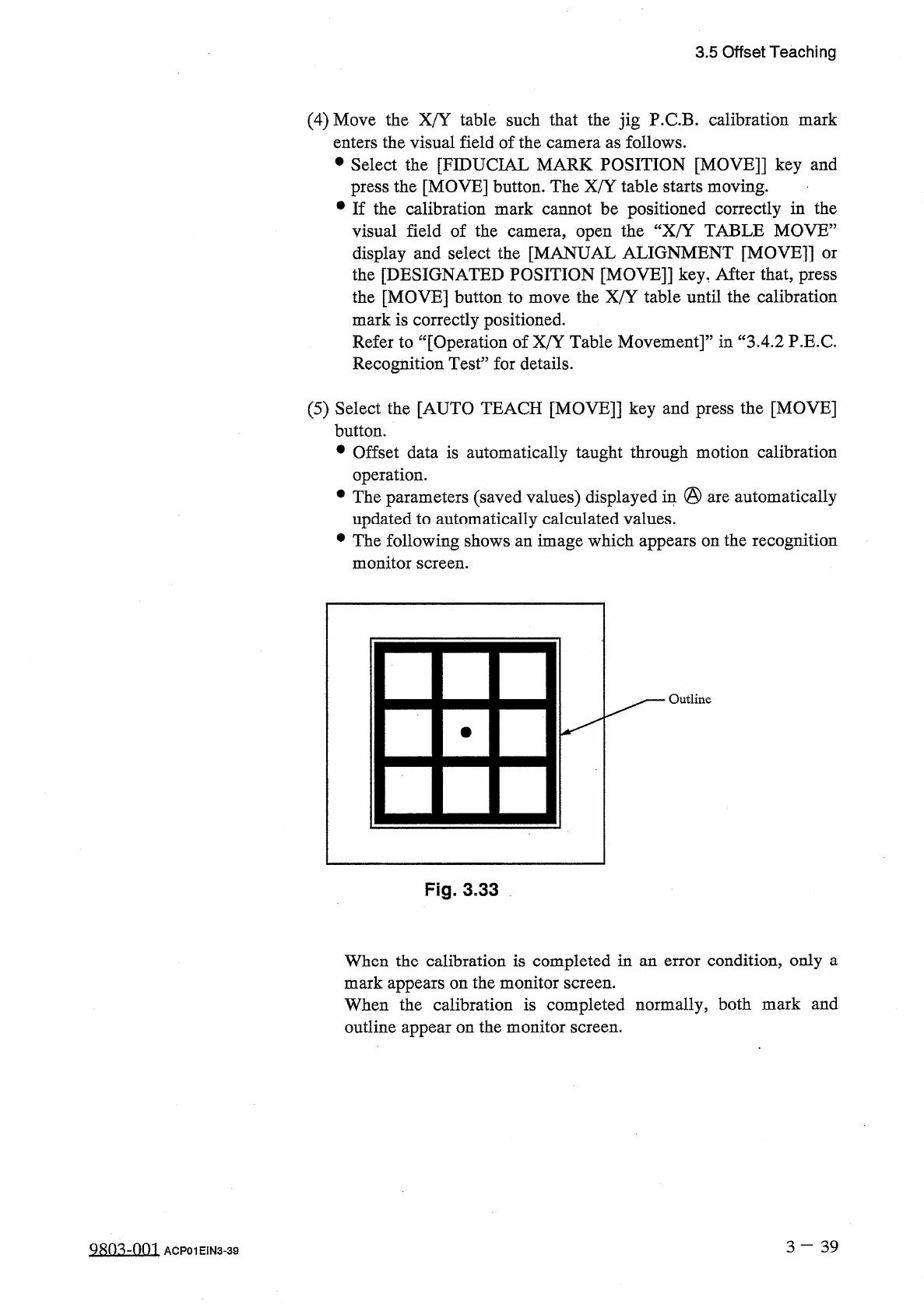
•
The
following
shows
an
image
which
appears
on
the
recognition
monitor
screen
.
Outline
Fig
.
3.33
When
the
calibration
is
completed
in
an
error
condition
,
only
a
mark
appears
on
the
monitor
screen
.
When
the
calibration
is
completed
normally
,
both
mark
and
outline
appear
on
the
monitor
screen
.
3
一
39
QRO
^
-
OOI
ACP
01
EIN
3
-
39