3MAINTENANCE__O.pdf - 第143页
3.7 Unit Adjustment 3.7 Unit Adjustment When the [ UNIT ADJUSTMENT ] key is pressed at the “ SPECIAL SEL . ” display , the following display appears on the screen . l ^ N U UNIT ADJUSTMENT FEEDER UHIT NOZZLE ADJUSTMENT C…
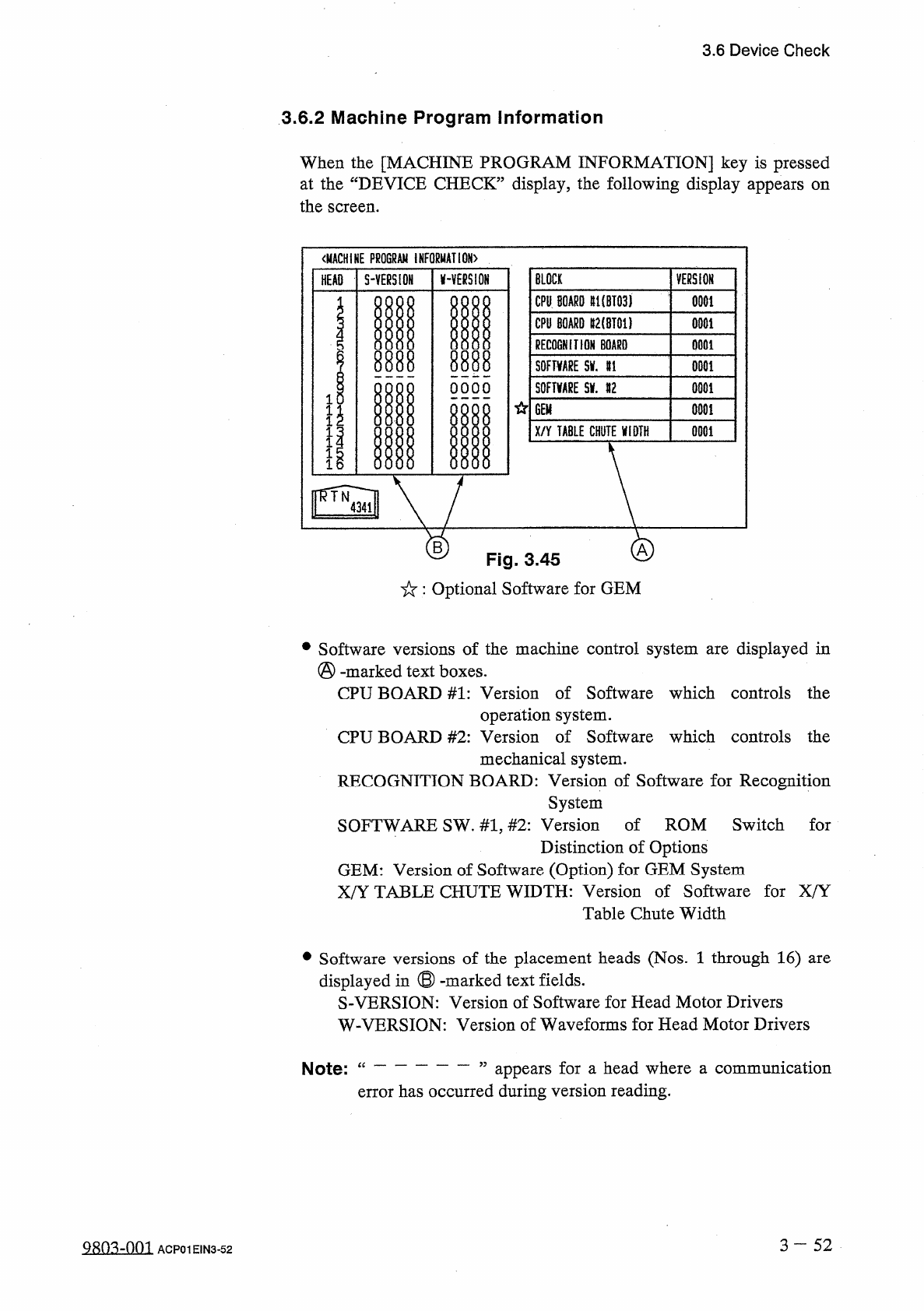
3.6
Device
Check
3.6
.
2
Machine
Program
Information
When
the
[
MACHINE
PROGRAM
INFORMATION
]
key
is
pressed
at
the
“
DEVICE
CHECK
”
display
,
the
following
display
appears
the
screen
.
on
〈
MACHINE
PROGRAM
INFORMATION
)
BLOCK
S
-
YERS
10
H
AVERSION
VERSION
HEAD
CPU
BOARD
#
1
(
BT
03
)
0001
CPU
BOARD
lt
2
(
BT
01
)
0001
RECOGNITION
BOARD
0001
m
8888
SOFTWARE
5
V
.
U
0001
S
0
FTWRE
Slf
.
#
2
OOOO
0001
1
GEM
0001
I
1
X
/
Y
TABLE
CHUTE
WIDTH
0001
1
B
Fig
.
3.45
:
Optional
Software
for
GEM
•
Software
versions
of
the
machine
control
system
are
displayed
in
(
§
)
-
marked
text
boxes
.
CPU
BOARD
#
1
:
Version
of
Software
which
controls
the
operation
system
.
CPU
BOARD
#
2
:
Version
of
Software
which
controls
the
mechanical
system
.
RECOGNITION
BOARD
:
Version
of
Software
for
Recognition
System
SOFTWARE
SW
.
#
1
,
#
2
:
Version
of
ROM
Switch
for
Distinction
of
Options
GEM
:
Version
of
Software
(
Option
)
for
GEM
System
X
/
Y
TABLE
CHUTE
WIDTH
:
Version
of
Software
for
X
/
Y
Table
Chute
Width
of
the
placement
heads
(
Nos
.
1
through
16
)
are
•
Software
displayed
in
®
-
marked
text
fields
.
S
-
VERSION
:
Version
of
Software
for
Head
Motor
Drivers
versions
W
-
VERSION
:
Version
of
Waveforms
for
Head
Motor
Drivers
appears
for
a
head
where
a
communication
error
has
occurred
during
version
reading
.
Note
:
“
3
-
52
QRQ
^
-
001
ACP
01
EIN
3
-
52
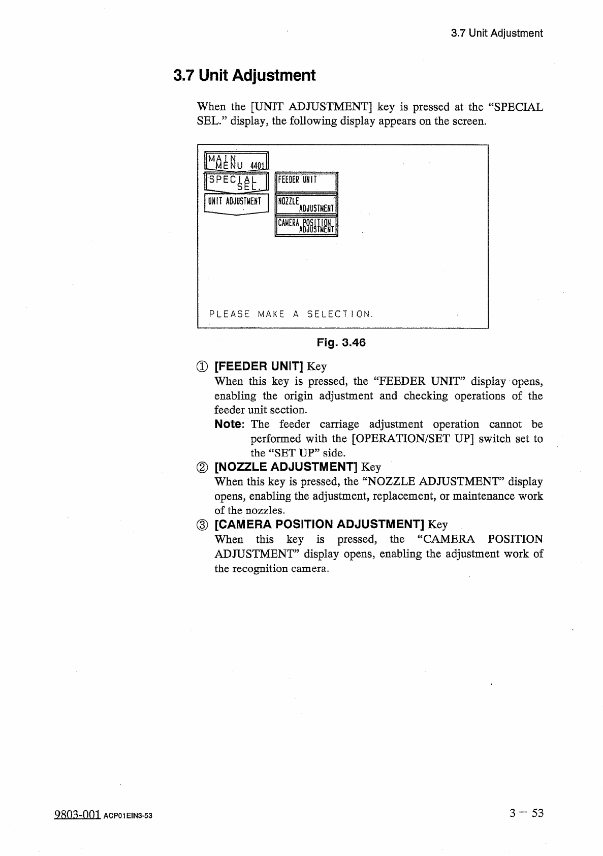
3.7
Unit
Adjustment
3.7
Unit
Adjustment
When
the
[
UNIT
ADJUSTMENT
]
key
is
pressed
at
the
“
SPECIAL
SEL
.
”
display
,
the
following
display
appears
on
the
screen
.
l
^
N U
UNIT
ADJUSTMENT
FEEDER
UHIT
NOZZLE
ADJUSTMENT
CAMERA
ASJUSIMPNT
PLEASE
MAKE
A
SELECT
1
ON
.
Fig
.
3.46
①
[
FEEDER
UNIT
]
Key
When
this
key
is
pressed
,
the
“
FEEDER
UNIT
”
display
opens
,
enabling
the
origin
adjustment
and
checking
operations
of
the
feeder
unit
section
.
Note
:
The
feeder
carriage
adjustment
operation
cannot
be
performed
with
the
[
OPERATION
/
SET
UP
]
switch
set
to
the
“
SET
UP
”
side
.
②
[
NOZZLE
ADJUSTMENT
]
Key
When
this
key
is
pressed
,
the
opens
,
enabling
the
adjustment
,
replacement
,
or
maintenance
work
of
the
nozzles
.
③
[
CAMERA
POSITION
ADJUSTMENT
]
Key
When
this
key
is
pressed
,
the
ADJUSTMENT
”
display
opens
,
enabling
the
adjustment
work
of
the
recognition
camera
.
display
fNOZZLE
ADJUSTMENT
”
CAMERA
POSITION
3
—
5 3
9803
-
001
ACP
01
EIN
3
-
53
3.7
Unit
Adjustment
3.7
.
1
Feeder
Unit
When
the
[
FEEDER
UNIT
]
key
is
pressed
at
the
“
UNIT
ADJUSTMENT
”
display
,
the
following
display
appears
on
the
screen
.
N
M
STATUS
DESCRIPTION
NU
4411
ORIGIN
)
ORIGIN
十
…
1
ORIGIN
十
…
1
ORIGIN
ORIGIN
•
(
——
}
ORIGIN
FOR
.
CARRIAGE
AXIS
MOTOR
U
ORIGIN
!
!
EC
^
L
FOR
.
CARRIAGE
AXIS
MOTOR
U
MIDDLE
ORIGIN
ORIGIN
UNIT
ADJUSTMENT
FOR
.
CARRIAGE
AXIS
MOTOR
U
ORIGIN
ORIGIN
FEEDER
UNIT
FDR
.
CARRIAGE
AXIS
MOTOR
»
2
MIDDLE
ORIGIN
FDR
.
CARRIAGE
AXIS
MOTOR
ttU
2
ORIGIN
ORIGIN
FDR
.
CARRIAGE
AXIS
MOTOR
gU
2
MIDDLE
ORIGIN
SELECT
THE
DESCRIPTION
&
PRESS
THE
[
MOVEI
BUTTON
.
Fig
.
3.47
The
menus
are
used
to
adjust
the
origin
of
the
feeder
unit
section
and
perform
the
check
operations
.
Notes
:
(
a
)
These
menus
are
used
by
our
service
personnel
.
(
b
)
Only
the
operations
on
the
rear
touch
panel
become
valid
.
No
operations
on
the
front
touch
panel
are
possible
.
•
When
of
the
keys
under
the
label
“
DESCRIPTION
”
is
selected
and
the
[
MOVE
]
button
is
pressed
,
the
selected
device
to
its
origin
position
and
“
ORIGIN
”
appears
in
the
corresponding
“
STATUS
”
text
box
.
one
moves
3
-
5 4
0107
-
002
ACP
01
EIN
3
-
54