3MAINTENANCE__O.pdf - 第145页
3.7 Unit Adjustment 3.7 . 2 Nozzle Adjustment When the [ NOZZLE ADJUSTMENT ] key is pressed at the “ UNIT ADJUSTMENT ” display , the following display appears on the screen . < H 0 ZZLE ADJUSTMENT 〉 DESIGNATE HEAD ALL…
3.7
Unit
Adjustment
3.7
.
1
Feeder
Unit
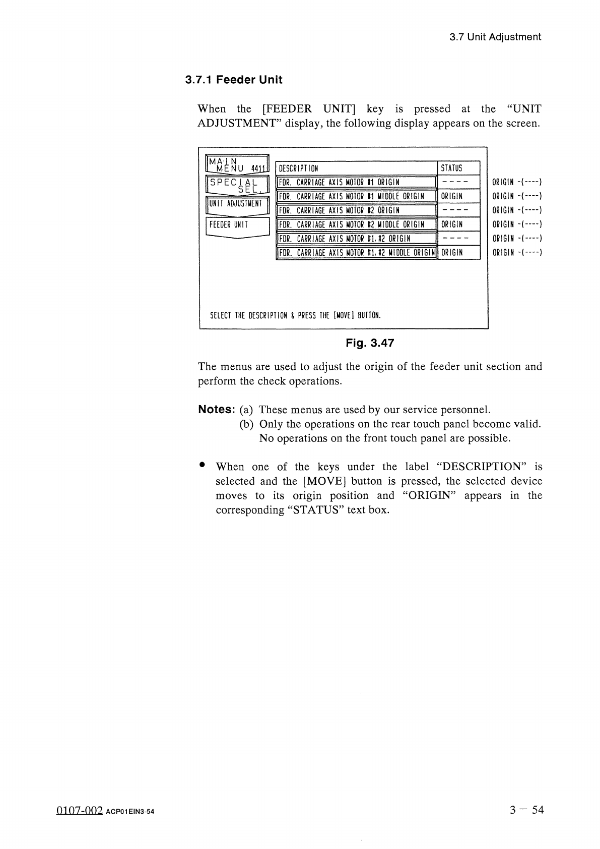
When
the
[
FEEDER
UNIT
]
key
is
pressed
at
the
“
UNIT
ADJUSTMENT
”
display
,
the
following
display
appears
on
the
screen
.
N
M
STATUS
DESCRIPTION
NU
4411
ORIGIN
)
ORIGIN
十
…
1
ORIGIN
十
…
1
ORIGIN
ORIGIN
•
(
——
}
ORIGIN
FOR
.
CARRIAGE
AXIS
MOTOR
U
ORIGIN
!
!
EC
^
L
FOR
.
CARRIAGE
AXIS
MOTOR
U
MIDDLE
ORIGIN
ORIGIN
UNIT
ADJUSTMENT
FOR
.
CARRIAGE
AXIS
MOTOR
U
ORIGIN
ORIGIN
FEEDER
UNIT
FDR
.
CARRIAGE
AXIS
MOTOR
»
2
MIDDLE
ORIGIN
FDR
.
CARRIAGE
AXIS
MOTOR
ttU
2
ORIGIN
ORIGIN
FDR
.
CARRIAGE
AXIS
MOTOR
gU
2
MIDDLE
ORIGIN
SELECT
THE
DESCRIPTION
&
PRESS
THE
[
MOVEI
BUTTON
.
Fig
.
3.47
The
menus
are
used
to
adjust
the
origin
of
the
feeder
unit
section
and
perform
the
check
operations
.
Notes
:
(
a
)
These
menus
are
used
by
our
service
personnel
.
(
b
)
Only
the
operations
on
the
rear
touch
panel
become
valid
.
No
operations
on
the
front
touch
panel
are
possible
.
•
When
of
the
keys
under
the
label
“
DESCRIPTION
”
is
selected
and
the
[
MOVE
]
button
is
pressed
,
the
selected
device
to
its
origin
position
and
“
ORIGIN
”
appears
in
the
corresponding
“
STATUS
”
text
box
.
one
moves
3
-
5 4
0107
-
002
ACP
01
EIN
3
-
54
3.7
Unit
Adjustment
3.7
.
2
Nozzle
Adjustment
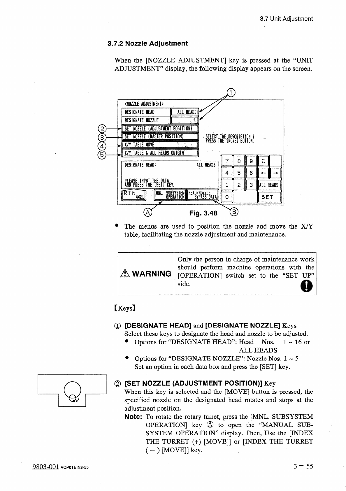
When
the
[
NOZZLE
ADJUSTMENT
]
key
is
pressed
at
the
“
UNIT
ADJUSTMENT
”
display
,
the
following
display
appears
on
the
screen
.
<
H
0
ZZLE
ADJUSTMENT
〉
DESIGNATE
HEAD
ALL
HEADS
DESIGNATE
NOZZLE
②
I
SET
NOZZLE
1
ADJUSTMENT
POSITIDNT
I
SET
NOZZLE
(
MASTER
POSITION
)
腿
IX
/
Y
TABLE
HOVE
'
ix
/
Y
TABLE
t
ALL
HEADS
QKIGIN
]
©
?
8
9
C
DESIGNATE
HEAD
:
All
HEADS
4
5
6
龇器
EffVMfk
2
3
ALL
HEADS
1
腦
HEA
»
Lk
MNL
.
4421
0
SET
Fig
.
3.48
•
The
used
to
position
the
nozzle
and
move
the
X
/
Y
table
,
facilitating
the
nozzle
adjustment
and
maintenance
.
menus
are
Only
the
person
in
charge
of
maintenance
work
should
perform
machine
operations
with
the
[
OPERATION
]
switch
set
to
the
“
SET
UP
,,
side
.
A
WARNING
o
[
Keys
]
①
[
DESIGNATE
HEAD
]
and
[
DESIGNATE
NOZZLE
]
Keys
Select
these
keys
to
designate
the
head
and
nozzle
to
be
adjusted
.
•
Options
for
“
DESIGNATE
HEAD
”
:
Head
Nos
.
1
~
16
or
ALL
HEADS
•
Options
for
“
DESIGNATE
NOZZLE
”
:
Nozzle
Nos
.
1
~
5
Set
an
option
in
each
data
box
and
press
the
[
SET
]
key
.
②
[
SET
NOZZLE
(
ADJUSTMENT
POSITION
)
]
Key
When
this
key
is
selected
and
the
[
MOVE
]
button
is
pressed
,
the
specified
nozzle
on
the
designated
head
rotates
and
stops
at
the
adjustment
position
.
Note
:
To
rotate
the
rotary
turret
,
press
the
[
MNL
.
SUBSYSTEM
OPERATION
]
key
@
to
open
the
“
MANUAL
SUB
-
SYSTEM
OPERATION
”
display
.
Then
,
Use
the
[
INDEX
THE
TURRET
(
+
)
[
MOVE
]]
or
[
INDEX
THE
TURRET
(
-
)
[
MOVE
]
]
key
.
Q
3
-
55
Q
80
^
-
001
ACP
01
EIN
3
-
55
3.7
Unit
Adjustment
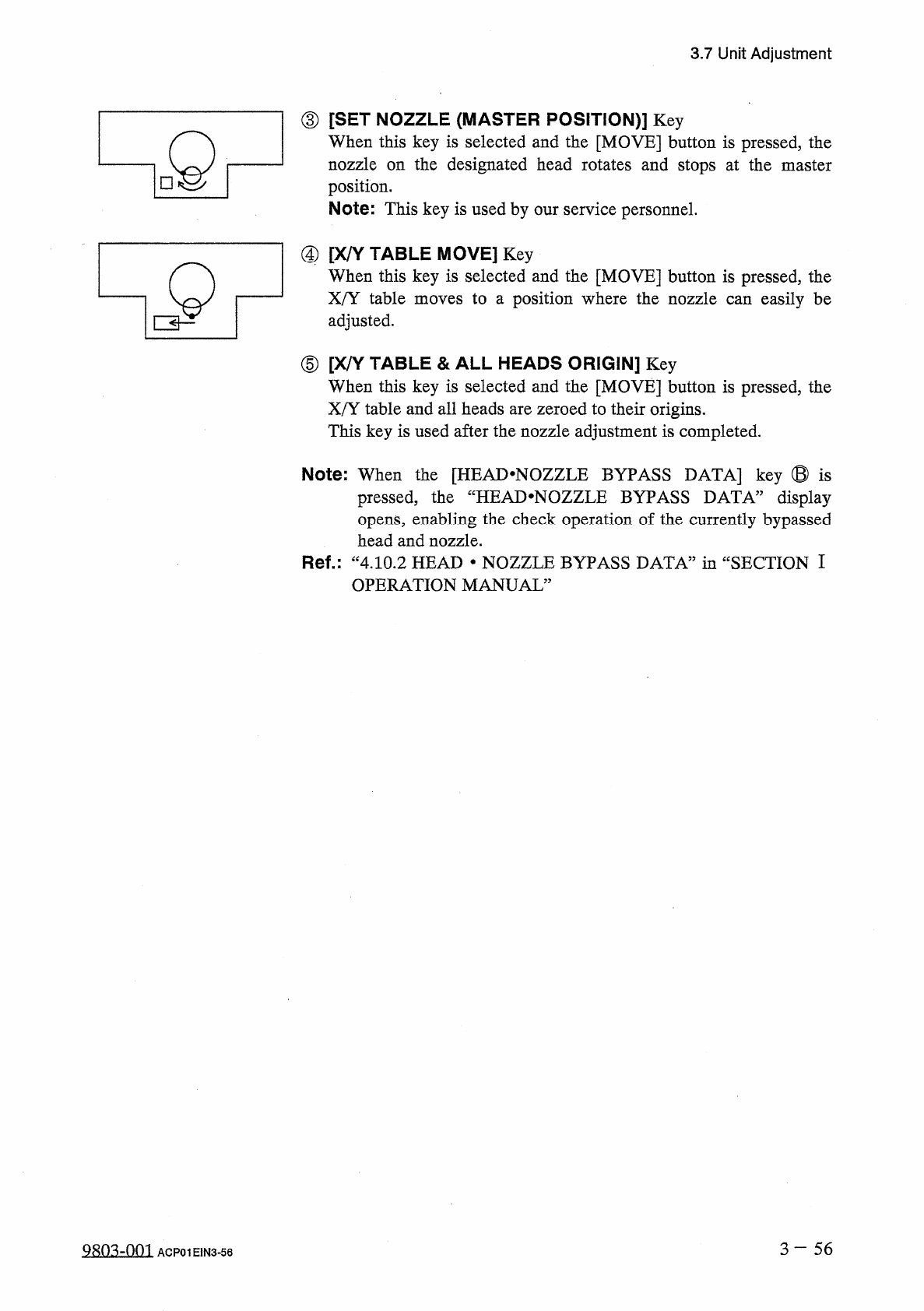
③
[
SET
NOZZLE
(
MASTER
POSITION
)
]
Key
When
this
key
is
selected
and
the
[
MOVE
]
button
is
pressed
,
the
nozzle
on
the
designated
head
rotates
and
stops
at
the
master
position
.
Note
:
This
key
is
used
by
our
service
personnel
.
dQ
④
[
X
/
Y
_
When
TABLE
MOVE
]
Key
this
key
is
selected
and
the
[
MOVE
]
button
is
pressed
,
the
X
/
Y
table
moves
to
a
position
where
the
nozzle
can
easily
be
adjusted
.
⑤
[
X
/
Y
-
When
TABLE
&
ALL
HEADS
ORIGIN
]
Key
this
key
is
selected
and
the
[
MOVE
]
button
is
pressed
,
the
X
/
Y
table
and
all
heads
are
zeroed
to
their
origins
.
This
key
is
used
after
the
nozzle
adjustment
is
completed
.
Note
:
When
the
[
HEAD
*
NOZZLE
BYPASS
DATA
]
key
®
is
pressed
,
the
“
HEAD
*
NOZZLE
BYPASS
DATA
”
display
opens
,
enabling
the
check
operation
of
the
currently
bypassed
head
and
nozzle
.
Ref
.
:
“
4.10
.
2
HEAD
•
NOZZLE
BYPASS
DATA
”
in
“
SECTION
I
OPERATION
MANUAL
”
3
一
56
QRO
^
-
nm
ACP
01
E
1
N
3
-
56