3MAINTENANCE__O.pdf - 第194页
4.4 Setting of Light Tower and Alarm Data • When the [ DEFAULT VALUES ] key is pressed , default parameters are set as follows . MACHINE STATUS RED YELLOW GREEN ALARM MODE OH irOFF H OFF II QN ( CONTIHWS ) EMERGENCY STOP…
4.4
Setting
of
Light
Tower
and
Alarm
Data
4.4
Setting
of
Light
Tower
and
Alarm
Data
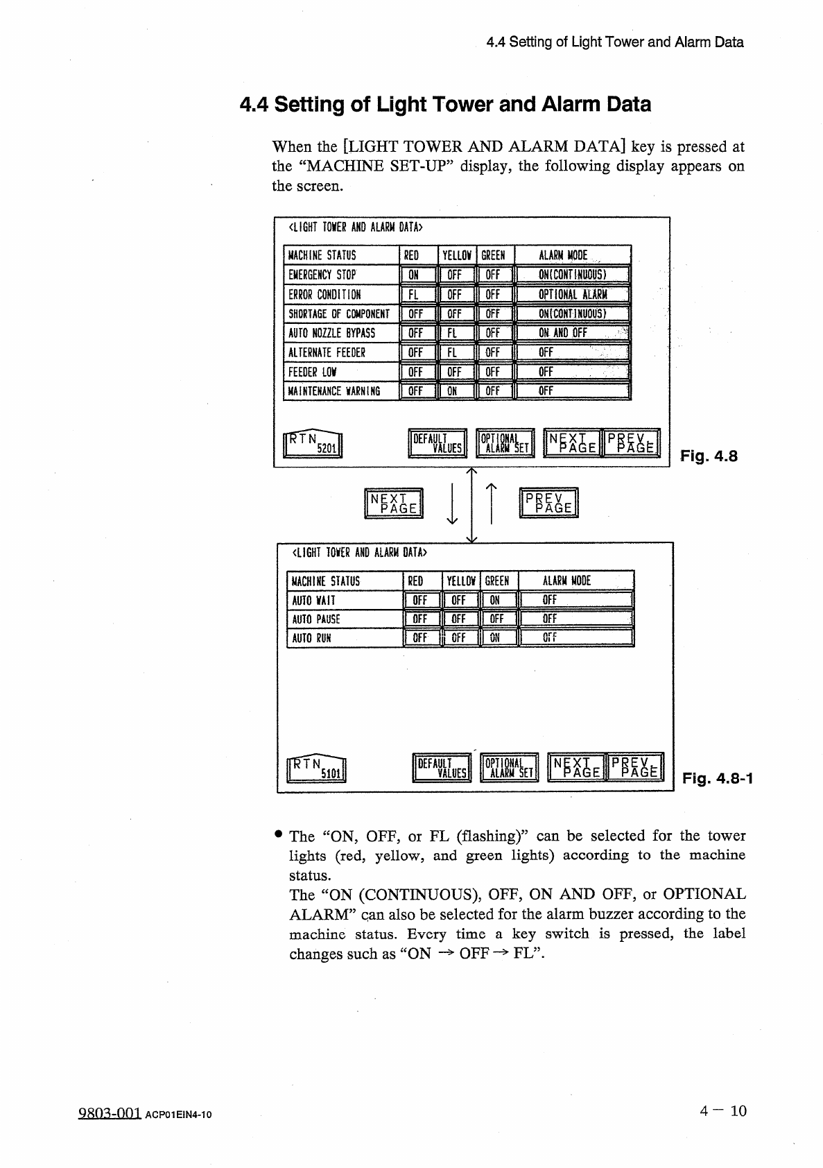
When
the
[
LIGHT
TOWER
AND
ALARM
DATA
]
key
is
pressed
at
the
“
MACHINE
SET
-
UP
”
display
,
the
following
display
appears
on
the
screen
.
〈
LIGHT
TOKR
AND
ALARM
0
AtA
>
MACHINE
STATUS
RED
YELLOV
GREEN
ALARM
MODE
[
IFF
ONtCONTHWOHS
)
OFF
EMERGENCY
STOP
ON
ffi
opTioHAi
mm
ERROR
CONDITION
OFF
FL
QN
(
CONTlNljQUS
)
OFF
SHORTAGE
DF
CWiPONEMT
OFF
Ofi
AND
OFF
AUTO
NOZZLE
BYPASS
OFF
OFF
Ft
OFF
ALTERNATE
FEEDER
OFF
FL
OFF
m
Of
OFF
OFF
OFF
FEEDER
LOV
OFF
OFF
MAINTENANCE
VARNIK
6
OFF
pgy
Fig
.
4.8
PRP
^
E
NPAGE
<
LIGHT
I
0
KR
AND
ALARM
DATA
〉
ALARM
MODE
GREEN
MACHINE
STATUS
RED
YELLOV
OFF
OFF
OFF
AUTO
VAII
ON
OFF
OFF
OFF
OFF
AUTO
PAUSE
or
?
OFF
OFF
ON
AUTO
m
DEFA
&
S
p
^
h
Fig
.
4.8
-
1
•
The
“
ON
,
OFF
,
or
FL
(
flashing
)
”
can
be
selected
for
the
tower
lights
(
red
,
yellow
,
and
green
lights
)
according
to
the
machine
status
.
The
“
ON
(
CONTINUOUS
)
,
OFF
,
ON
AND
OFF
,
or
OPTIONAL
ALARM
”
qan
also
be
selected
for
the
alarm
buzzer
according
to
the
machine
status
.
Every
time
a
key
switch
is
pressed
,
the
label
changes
such
as
ON
—
OFF
—
FL
”
.
4
-
10
9803
-
QQ
1
ACP
01
EIN
4
-
10
4.4
Setting
of
Light
Tower
and
Alarm
Data
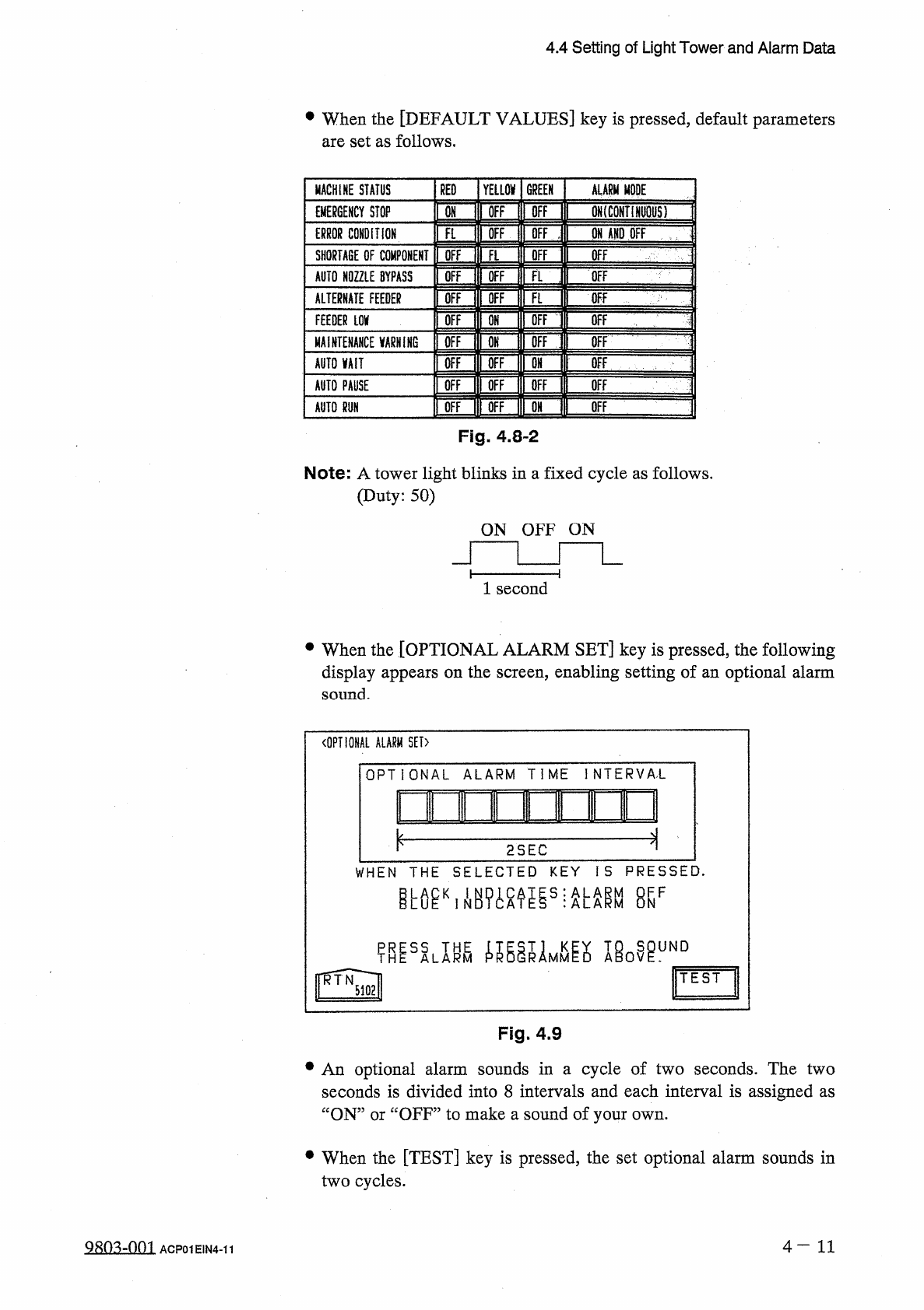
•
When
the
[
DEFAULT
VALUES
]
key
is
pressed
,
default
parameters
are
set
as
follows
.
MACHINE
STATUS
RED
YELLOW
GREEN
ALARM
MODE
OH
irOFF
H
OFF
II
QN
(
CONTIHWS
)
EMERGENCY
STOP
Eflil
IH
II
ON
AND
OFF
—
ERROR
CONDITION
OFF
SHORTAGE
OF
COMPONENT
OFF
AUTO
NOZZLE
BYPASS
OFF
OFF
OFF
ALTERNATE
FEEDER
\
\
mm
\
ii
丽
FEEDER
LOV
OFF
MAINTENANCE
VARNiNG
[
OFF
OFF
rOFFlrOFF
OFF
AUTO
MIT
i
画
i
—
j
丽
ii
!
Wiin
»
OFF
AUTO
PAUSE
OFF
AUTO
m
Fig
.
4.8
-
2
Note
:
A
tower
light
blinks
in
a
fixed
cycle
as
follows
.
(
Duty
:
50
)
ON
OFF
ON
1
second
•
When
the
[
OPTIONAL
ALARM
SET
]
key
is
pressed
,
the
following
display
appears
on
the
screen
,
enabling
setting
of
an
optional
alarm
sound
.
〈
OPTIONAL
ALARM
SET
)
OPTIONAL
ALARM
TIME
INTERVA
'
L
innir
—
m
—
.
i
i
ui
2
SEC
WHEN
THE
SELECTED
KEY
IS
PRESSED
.
esF
miLm
ie
0
^
uND
TEST
Fig
.
4.9
•
An
optional
alarm
sounds
in
a
cycle
of
two
seconds
.
The
two
seconds
is
divided
into
8
intervals
and
each
interval
is
assigned
as
“
ON
”
or
“
OFF
”
to
make
a
sound
of
your
own
.
•
When
the
[
TEST
]
key
is
pressed
,
the
set
optional
alarm
sounds
in
two
cycles
.
4
—
1 1
糊
:
Vf
)
01
ACP
01
EIN
4
-
11
4.5
Setting
of
Date
and
Time
Data
4.5
Setting
of
Date
and
Time
Data
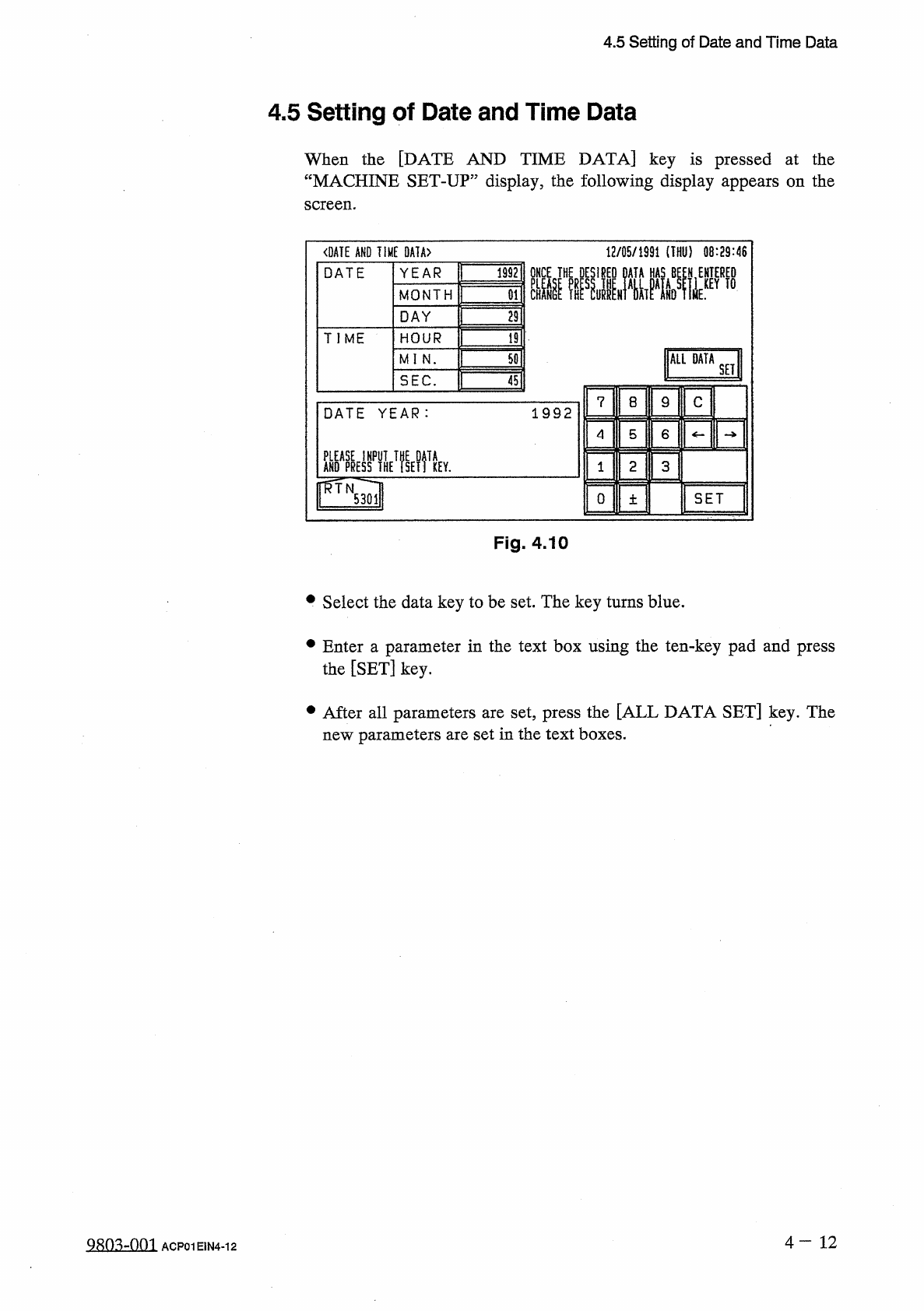
When
the
[
DATE
AND
TIME
DATA
]
key
is
pressed
at
the
“
MACHINE
SET
-
UP
”
display
,
the
following
display
appears
on
the
screen
.
<
DATE
AND
TIME
0
A
1
A
>
12
/
05
/
1991
(
THU
)
08
:
29
:
46
ONCE
THE
DESIRED
DATA
HAS
BE
£
N
,
ENTERED
YEAR
1992
DATE
MONTH
29
DAY
TIME
HOUR
19
ALL
DATA
50
MI
N
.
SET
SEC
.
45
C
7
8
9
1992
DATE
YEAR
:
4
5
6
AHO
^
yffHE
^
SElftEY
.
ffTN
2
3
SET
0
5301
土
Fig
.
4.10
•
Select
the
data
key
to
be
set
.
The
key
turns
blue
.
•
Enter
a
parameter
in
the
text
box
using
the
ten
-
key
pad
and
press
the
[
SET
]
key
.
•
After
all
parameters
are
set
,
press
the
[
ALL
DATA
SET
]
key
.
The
new
parameters
are
set
in
the
text
boxes
.
4
一
12
98
Q
3
..
-
.
.
Q
.
Q
1
ACP
01
E
1
N
4
-
12