3MAINTENANCE__O.pdf - 第42页
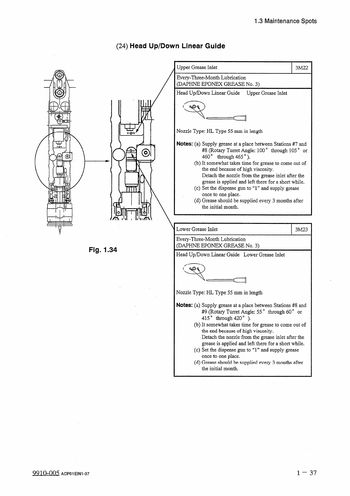
1.3 Maintenance Spots ( 24 ) Head Up / Down Linear Guide Upper Grease Inlet 3 M 22 Eveiy - Three - Month Lubrication ( DAPHNE EPQNEX GREASE No . 3 ) Head Up / Down Linear Guide Upper Grease Inlet Nozzle Type : HL Type 55…
1.3
Maintenance
Spots
o
o
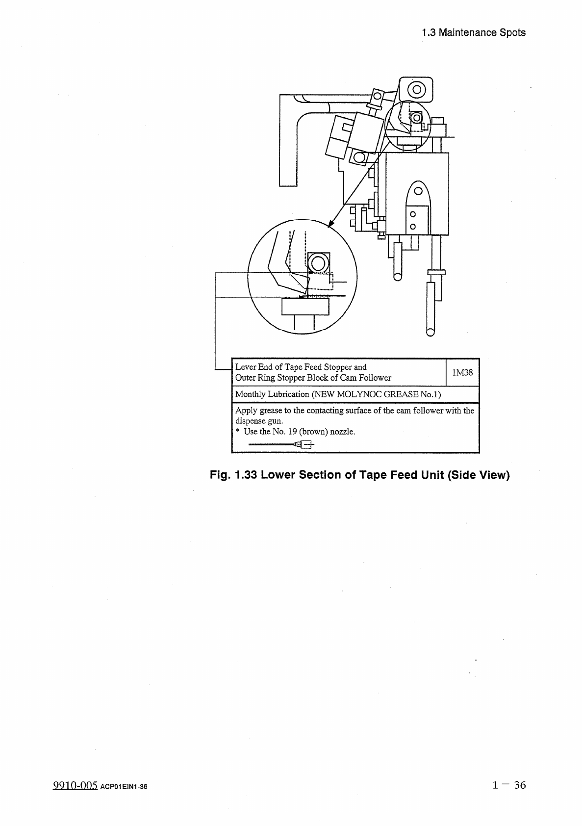
Lever
End
of
Tape
Feed
Stopper
and
Outer
Ring
Stopper
Block
of
Cam
Follower
1
M
38
Monthly
Lubrication
(
NEW
MOLYNOC
GREASE
No
.
l
)
Apply
grease
to
the
contacting
surface
of
the
cam
follower
with
the
dispense
gun
.
*
Use
the
No
.
19
(
brown
)
nozzle
.
Fig
.
1.33
Lower
Section
of
Tape
Feed
Unit
(
Side
View
)
1
—
36
叫
10
-
005
ACP
01
E
1
N
1
-
36
1.3
Maintenance
Spots
(
24
)
Head
Up
/
Down
Linear
Guide
Upper
Grease
Inlet
3
M
22
Eveiy
-
Three
-
Month
Lubrication
(
DAPHNE
EPQNEX
GREASE
No
.
3
)
Head
Up
/
Down
Linear
Guide
Upper
Grease
Inlet
Nozzle
Type
:
HL
Type
55
mm
in
length
Notes
:
(
a
)
Supply
grease
at
a
place
between
Stations
#
7
and
#
8
(
Rotaiy
Turret
Angle
:
100
°
through
1050
460
。
through
465
°
)
.
(
b
)
It
somewhat
takes
time
for
grease
to
come
out
of
the
end
because
of
high
viscosity
.
Detach
the
nozzle
from
the
grease
inlet
after
the
grease
is
applied
and
left
there
for
a
short
while
.
(
c
)
Set
the
dispense
gun
to
“
1
”
and
supply
grease
once
to
one
place
.
(
d
)
Grease
should
be
supplied
every
3
months
after
the
initial
month
.
or
ol
Lower
Grease
Inlet
3
M
23
Eveiy
-
Three
-
Month
Lubrication
(
DAPHNE
EPQNEX
GREASE
No
.
3
)
Fig
.
1.34
Head
Up
/
Down
Linear
Guide
Lower
Grease
Inlet
c
=
t
Nozzle
Type
:
HL
Type
55
mm
in
length
Notes
:
(
a
)
Supply
grease
at
a
place
between
Stations
#
8
and
#
9
(
Rotaiy
Turret
Angle
:
55
°
through
60
°
415
。
through
420
。
)
.
(
b
)
It
somewhat
takes
time
for
grease
to
come
out
of
the
end
because
of
high
viscosity
.
Detach
the
nozzle
from
the
grease
inlet
after
the
grease
is
applied
and
left
there
fora
short
while
.
(
c
)
Set
the
dispense
gun
to
“
1
”
and
supply
grease
once
to
one
place
.
(
d
)
Grease
should
be
supplied
every
3
months
after
the
initial
month
.
or
1
-
37
QQio
-
.
nn
5
ACP
01
EIN
1
-
37
1.3
Maintenance
Spots
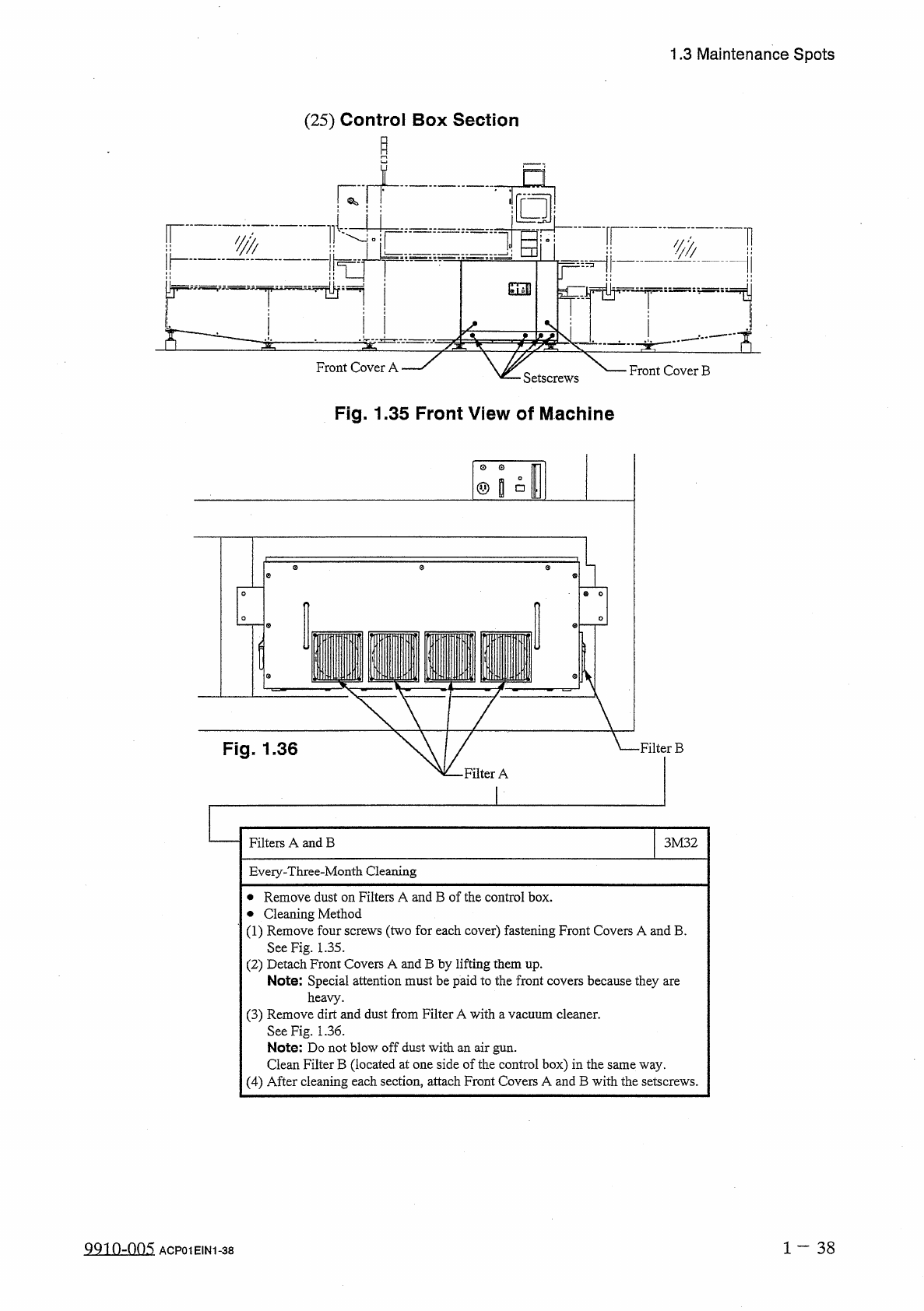
(
25
)
Control
Box
Section
「
"
,
n
3
——
ii
r
:
:
,
■
‘
丄
'
—
Front
Cover
A
Front
Cover
B
Setscrews
Fig
.
1.35
Front
View
of
Machine
@
s
°
(
Fig
.
1.36
•
Filter
B
•
Filter
A
Filters
A
and
B
3
M
32
Eveiy
-
Three
-
Month
Cleaning
•
Remove
dust
on
Filters
A
and
B
of
the
control
box
.
•
Cleaning
Method
(
1
)
Remove
four
screws
(
two
for
each
cover
)
fastening
Front
Covers
A
and
B
.
See
Fig
.
1.35
.
(
2
)
Detach
Front
Covers
A
and
B
by
lifting
them
up
.
Note
:
Special
attention
must
be
paid
to
the
front
covers
because
they
are
heavy
.
(
3
)
Remove
dirt
and
dust
from
Filter
A
with
a
vacuum
cleaner
.
See
Fig
.
1.36
.
Note
:
Do
not
blow
off
dust
with
an
air
gun
.
Clean
Filter
B
(
located
at
one
side
of
the
control
box
)
in
the
same
way
.
(
4
)
After
cleaning
each
section
,
attach
Front
Covers
A
and
B
with
the
setscrews
.
1
-
38
QQ
1
0
-
005
ACP
01
EIN
1
-
38