3MAINTENANCE__O.pdf - 第51页
1.4 Maintenance ( 2 ) Attachment of Vacuum Nozzle • Before attaching a vacuum nozzle , check that the end of the nozzle is not damaged , the tapered section is unscratched , the pick - up hole unclogged , and the grip se…
1.4
Maintenance
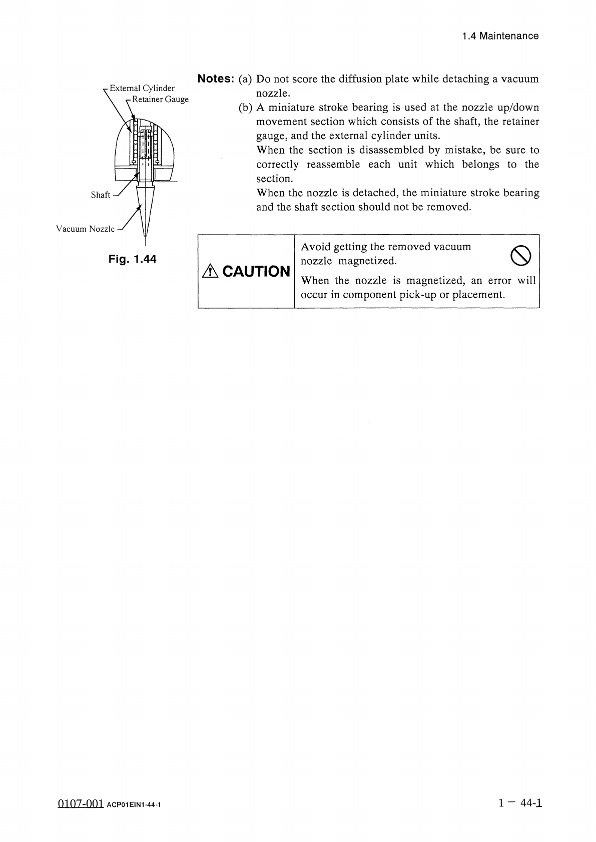
Notes
:
(
a
)
Do
not
score
the
diffusion
plate
while
detaching
a
vacuum
nozzle
.
(
b
)
A
miniature
stroke
bearing
is
used
at
the
nozzle
up
/
down
movement
section
which
consists
of
the
shaft
,
the
retainer
gauge
,
and
the
external
cylinder
units
.
When
the
section
is
disassembled
by
mistake
,
be
sure
to
correctly
reassemble
each
unit
which
belongs
to
the
section
.
When
the
nozzle
is
detached
,
the
miniature
stroke
bearing
and
the
shaft
section
should
not
be
removed
.
External
Cylinder
\
r
-
Retainer
Gauge
Vacuum
Nozzle
Avoid
getting
the
removed
vacuum
nozzle
magnetized
.
When
the
nozzle
is
magnetized
,
an
error
will
occur
in
component
pick
-
up
or
placement
.
(
S
>
Fig
.
1.44
A
CAUTION
1
—
44
-
1
0107
-
001
ACP
01
EIN
1
-
44
-
1
1.4
Maintenance
(
2
)
Attachment
of
Vacuum
Nozzle
•
Before
attaching
a
vacuum
nozzle
,
check
that
the
end
of
the
nozzle
is
not
damaged
,
the
tapered
section
is
unscratched
,
the
pick
-
up
hole
unclogged
,
and
the
grip
section
undeformed
.
•
Select
the
nozzle
which
meets
the
parameters
specified
in
the
placement
head
nozzle
data
.
•
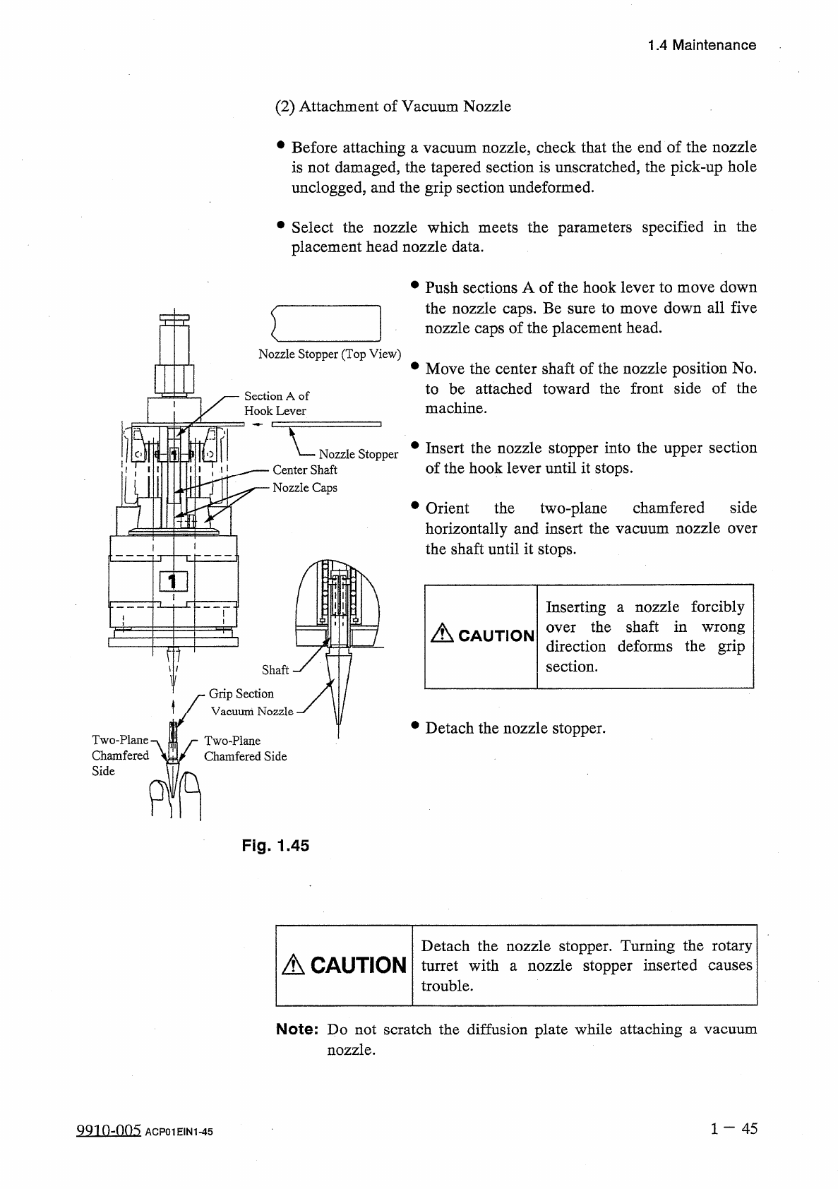
Push
sections
A
of
the
hook
lever
to
move
down
the
nozzle
caps
.
Be
sure
to
move
down
all
five
nozzle
caps
of
the
placement
head
.
Nozzle
Stopper
(
Top
View
)
•
Move
the
center
shaft
of
the
nozzle
position
No
.
to
be
attached
toward
the
front
side
of
the
machine
.
Section
A
of
Hook
Lever
•
Insert
the
nozzle
stopper
into
the
upper
section
of
the
hook
lever
until
it
stops
.
Nozzle
Stopper
Center
Shaft
Nozzle
Caps
•
Orient
the
two
-
plane
chamfered
side
horizontally
and
insert
the
vacuum
nozzle
over
the
shaft
until
it
stops
.
Inserting
a
nozzle
forcibly
over
the
shaft
in
wrong
direction
deforms
the
grip
section
.
A
CAUTION
TIT
Shaft
Grip
Section
Vacuum
Nozzle
•
Detach
the
nozzle
stopper
.
Two
-
Plane
•
Chamfered
Side
Two
-
Plane
Chamfered
Side
n
Fig
.
1.45
Detach
the
nozzle
stopper
.
Turning
the
rotary
turret
with
a
nozzle
stopper
inserted
trouble
.
A
CAUTION
causes
Note
:
Do
not
scratch
the
diffusion
plate
while
attaching
nozzle
.
a
vacuum
1
-
45
QQin
-
nn
5
ACP
01
EIN
1
-
45
1.4
Maintenance
(
3
)
Checking
of
Attached
Vacuum
Nozzle
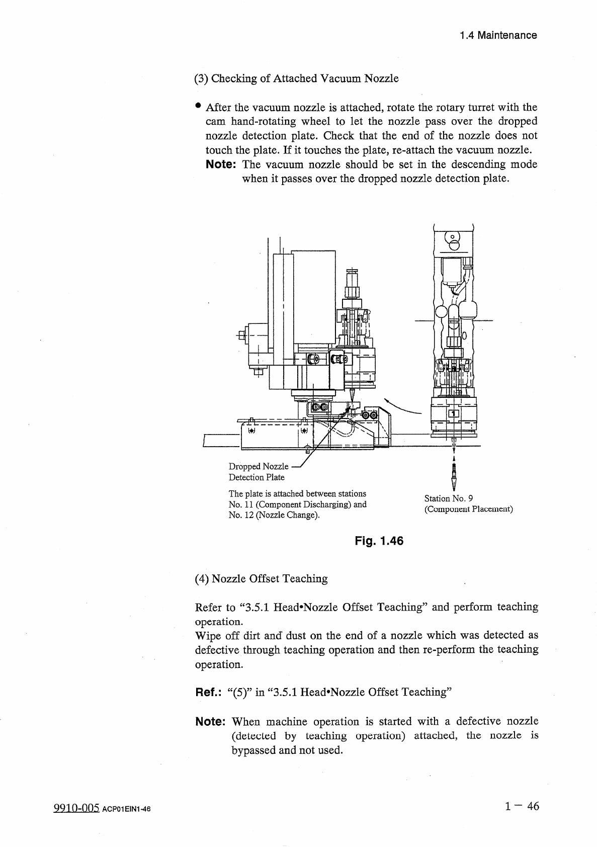
•
After
the
vacuum
nozzle
is
attached
,
rotate
the
rotary
turret
with
the
cam
hand
-
rotating
wheel
to
let
the
nozzle
pass
over
the
dropped
nozzle
detection
plate
.
Check
that
the
end
of
the
nozzle
does
not
touch
the
plate
.
If
it
touches
the
plate
,
re
-
attach
the
vacuum
nozzle
.
Note
:
The
vacuum
nozzle
should
be
set
in
the
descending
mode
when
it
passes
over
the
dropped
nozzle
detection
plate
.
fl
i
灘
lilil
i
!
riiiii
\
c
]
t
Dropped
Nozzle
Detection
Plate
The
plate
is
attached
between
stations
No
.
11
(
Component
Discharging
)
and
No
.
12
(
Nozzle
Change
)
.
Station
No
.
9
(
Component
Placement
)
Fig
.
1.46
(
4
)
Nozzle
Offset
Teaching
Refer
to
“
3.5
.
1
Head
*
Nozzle
Offset
Teaching
”
and
perform
teaching
operation
.
Wipe
off
dirt
and
*
dust
on
the
end
of
a
nozzle
which
was
detected
as
defective
through
teaching
operation
and
then
re
-
perform
the
teaching
operation
.
Ref
.
:
“
(
5
)
”
in
“
3.5
.
1
Head
#
Nozzle
Offset
Teaching
5
Note
:
When
machine
operation
is
started
with
a
defective
nozzle
(
detected
by
teaching
operation
)
attached
,
the
nozzle
is
bypassed
and
not
used
.
1
-
46
991
f
)
-
005
ACP
01
EIN
1
-
46