3MAINTENANCE__O.pdf - 第56页
1.4 Maintenance ⑤ Holder Attachment Follow the similar procedures described in “ ( 2 ) Disassembly Procedures ” and place the rotary joint tightening jig ( Standard Accessory Part ) in the two holes on the top of the DDM…
1.4
Maintenance
⑷
Reassembly
Procedures
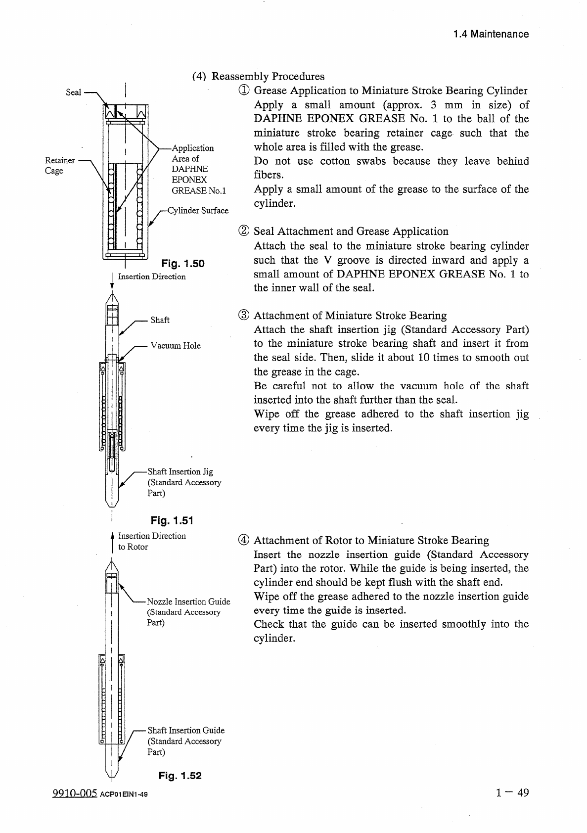
①
Grease
Application
to
Miniature
Stroke
Bearing
Cylinder
in
size
)
of
Seal
Apply
a
small
amount
(
approx
.
3
DAPHNE
EPONEX
GREASE
No
.
1
to
the
ball
of
the
miniature
stroke
bearing
retainer
cage
such
that
the
whole
area
is
filled
with
the
grease
.
Do
not
fibers
.
Apply
a
small
amount
of
the
grease
to
the
surface
of
the
cylinder
.
mm
-
Application
Area
of
DAPHNE
EPONEX
GREASE
No
.
1
cotton
swabs
because
they
leave
behind
Retainer
Cage
use
-
Cylinder
Surface
②
Seal
Attachment
and
Grease
Application
Attach
the
seal
to
the
miniature
stroke
bearing
cylinder
such
that
the
V
groove
is
directed
inward
and
apply
a
small
amount
of
DAPHNE
EPONEX
GREASE
No
.
1
to
the
inner
wall
of
the
seal
.
V
.
"
|
"
.
V
Fig
.
1.50
Insertion
Direction
A
串
③
Attachment
of
Miniature
Stroke
Bearing
Attach
the
shaft
insertion
jig
(
Standard
Accessory
Part
)
to
the
miniature
stroke
bearing
shaft
and
insert
it
from
the
seal
side
.
Then
,
slide
it
about
10
times
to
smooth
out
the
grease
in
the
cage
.
Be
careful
not
to
allow
the
vacuum
hole
of
the
shaft
inserted
into
the
shaft
further
than
the
seal
.
Wipe
off
the
grease
adhered
to
the
shaft
insertion
jig
every
time
the
jig
is
inserted
.
Shaft
Vacuum
Hole
ill
I
■
Shaft
Insertion
Jig
(
Standard
Accessory
Part
)
w
Fig
.
1.51
Insertion
Direction
to
Rotor
④
Attachment
of
Rotor
to
Miniature
Stroke
Bearing
Insert
the
nozzle
insertion
guide
(
Standard
Accessory
Part
)
into
the
rotor
.
While
the
guide
is
being
inserted
,
the
cylinder
end
should
be
kept
flush
with
the
shaft
end
.
Wipe
off
the
grease
adhered
to
the
nozzle
insertion
guide
every
time
the
guide
is
inserted
.
Check
that
the
guide
can
be
inserted
smoothly
into
the
cylinder
.
A
a
■
Nozzle
Insertion
Guide
(
Standard
Accessory
Part
)
I
Shaft
Insertion
Guide
(
Standard
Accessory
Part
)
y
Fig
.
1.52
1
一
49
QQ
10
-
005
ACP
01
EIN
1
-
49
1.4
Maintenance
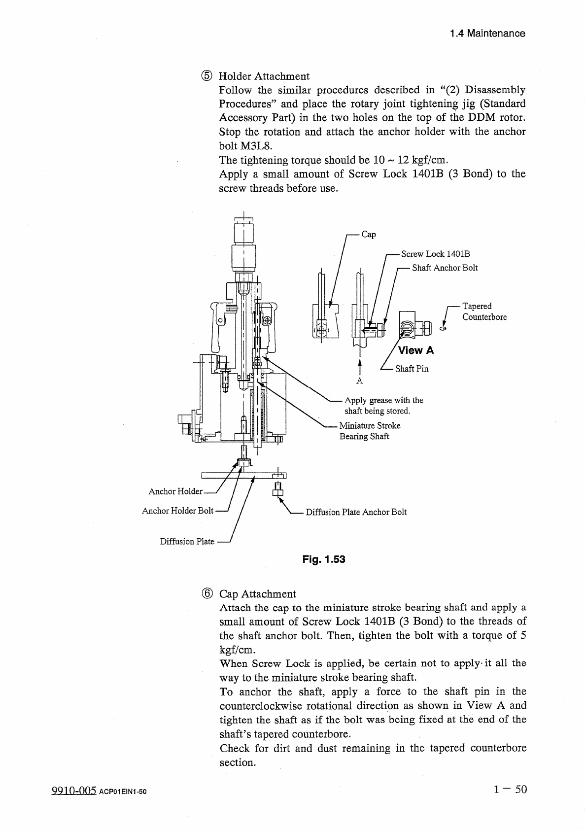
⑤
Holder
Attachment
Follow
the
similar
procedures
described
in
“
(
2
)
Disassembly
Procedures
”
and
place
the
rotary
joint
tightening
jig
(
Standard
Accessory
Part
)
in
the
two
holes
on
the
top
of
the
DDM
rotor
.
Stop
the
rotation
and
attach
the
anchor
holder
with
the
anchor
bolt
M
3
L
8
.
The
tightening
torque
should
be
10
12
kgf
/
cm
.
Apply
a
small
amount
of
Screw
Lock
1401
B
(
3
Bond
)
to
the
screw
threads
before
use
.
Screw
Lock
1401
B
Shaft
Anchor
Bolt
Tapered
Counterbore
Apply
grease
with
the
shaft
being
stored
.
匚
Miniature
Stroke
Bearing
Shaft
PI
]
T
]
Anchor
Holder
.
Anchor
Holder
Bolt
Diffusion
Plate
Anchor
Bolt
Diffusion
Plate
Fig
,
1.53
⑥
Cap
Attachment
Attach
the
cap
to
the
miniature
stroke
bearing
shaft
and
apply
a
small
amount
of
Screw
Lock
1401
B
(
3
Bond
)
to
the
threads
of
the
shaft
anchor
bolt
.
Then
,
tighten
the
bolt
with
a
torque
of
5
kgf
/
cm
.
When
Screw
Lock
is
applied
,
be
certain
not
to
apply
.
it
all
the
way
to
the
miniature
stroke
bearing
shaft
.
To
anchor
the
shaft
,
apply
a
force
to
the
shaft
pin
in
the
counterclockwise
rotational
direction
as
shown
in
View
A
and
tighten
the
shaft
as
if
the
bolt
was
being
fixed
at
the
end
of
the
shaft
’
s
tapered
counterbore
.
Check
for
dirt
and
dust
remaining
in
the
tapered
counterbore
section
.
1
-
50
QQ
10
-
005
ACP
01
EIN
1
-
50
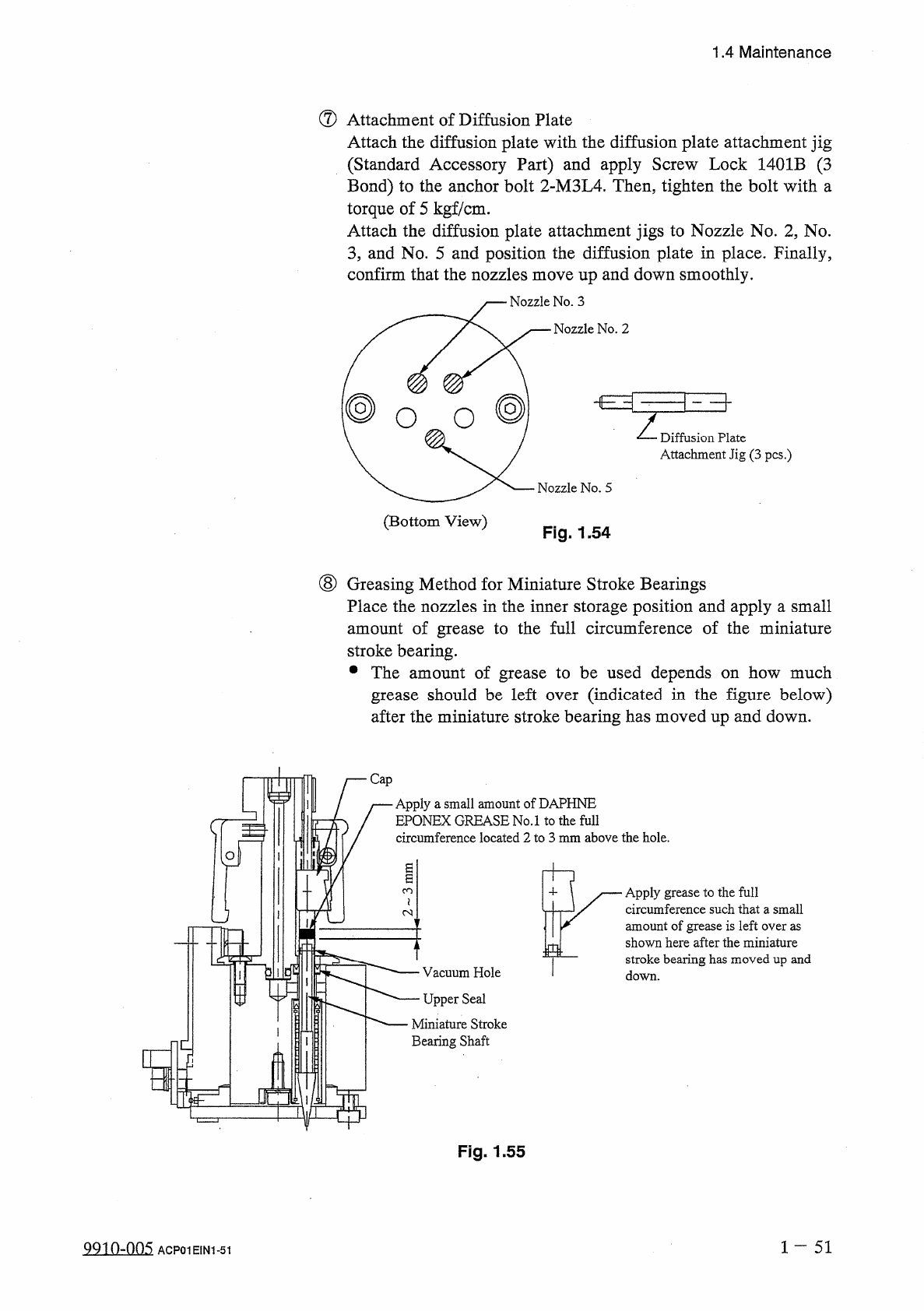
Vacuum
Hole
Upper
Seal
Apply
grease
to
the
full
circumference
such
that
a
small
amount
of
grease
is
left
over
as
shown
here
after
the
miniature
stroke
bearing
has
moved
up
and
down
.
H
—
Cap
Apply
a
small
amount
of
DAPHNE
EPONEX
GREASE
No
.
1
to
the
full
circumference
located
2
to
3
mm
above
the
hole
.
1.4
Maintenance
⑦
Attachment
of
Diffusion
Plate
Attach
the
diffusion
plate
with
the
diffusion
plate
attachment
jig
(
Standard
Accessory
Part
)
and
apply
Screw
Lock
1401
B
(
3
Bond
)
to
the
anchor
bolt
2
-
M
3
L
4
.
Then
,
tighten
the
bolt
with
a
torque
of
5
kgf
/
cm
.
Attach
the
diffusion
plate
attachment
jigs
to
Nozzle
No
.
2
,
No
.
3
,
and
No
.
5
and
position
the
diffusion
plate
in
place
.
Finally
,
confirm
that
the
nozzles
move
up
and
down
smoothly
.
j
—
Nozzle
No
.
3
Nozzle
No
.
2
@
O
O
Z
Diffusion
Plate
Attachment
Jig
(
3
pcs
.
)
Nozzle
No
.
5
(
Bottom
View
)
Fig
.
1.54
(
8
)
Greasing
Method
for
Miniature
Stroke
Bearings
Place
the
nozzles
in
the
inner
storage
position
and
apply
a
small
amount
of
grease
to
the
full
circumference
of
the
miniature
stroke
bearing
.
•
The
amount
of
grease
to
be
used
depends
on
how
much
grease
should
be
left
after
the
miniature
stroke
bearing
has
moved
up
and
down
.
(
indicated
in
the
figure
below
)
over
Miniature
Stroke
Bearing
Shaft
Q
Fig
.
1.55
1
~
51
Q
9
in
-
nn
5
ACP
01
EIN
1
-
51
UIUICO
iif