3MAINTENANCE__O.pdf - 第65页
1.4 Maintenance • Return the lever to the original position . • Put a new lamp in the lamp socket and push it down until it reaches the bottom of the lamp holder . At this time , direct the side of the lamp where the pro…
1.4
Maintenance
1.4
.
8
Lamp
Replacement
of
Light
Source
Device
(
1
)
Light
Source
Devices
Light
Source
Devices
:
MHF
-
DlOOLRSO
-
2
MHF
-
D
100
LRSC
-
2
:
LM
-
100
t
Lamp
(
2
)
Lamp
Replacement
Procedure
•
Turn
off
the
power
switch
of
the
light
source
device
and
check
that
the
LED
(
Orange
)
of
the
power
switch
extinguishes
.
Do
not
touch
the
lamp
right
after
it
has
been
turned
off
because
it
is
very
hot
.
Wait
for
about
3
to
5
minutes
or
until
it
cools
down
.
A
CAUTION
Be
sure
to
wear
gloves
made
of
thick
material
(
for
example
,
cotton
work
gloves
)
to
replace
the
lamp
right
after
it
has
been
turned
off
.
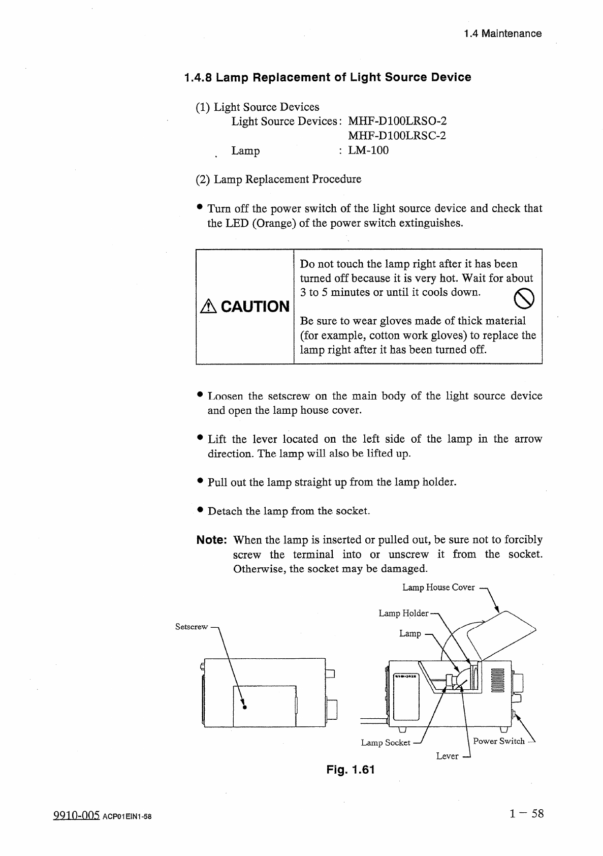
•
Loosen
the
setscrew
on
the
main
body
of
the
light
source
device
and
open
the
lamp
house
cover
.
•
Lift
the
lever
located
on
the
left
side
of
the
lamp
in
the
arrow
direction
.
The
lamp
will
also
be
lifted
up
.
•
Pull
out
the
lamp
straight
up
from
the
lamp
holder
.
•
Detach
the
lamp
from
the
socket
.
Note
:
When
the
lamp
is
inserted
or
pulled
out
,
be
sure
not
to
forcibly
screw
the
terminal
into
or
unscrew
it
from
the
socket
.
Otherwise
,
the
socket
may
be
damaged
.
Lamp
House
Cover
Lamp
Holder
.
Lamp
□
P
=
4
Lamp
Socket
Fig
.
1.61
1
-
58
991
0
-
005
ACP
01
EIN
1
-
58
1.4
Maintenance
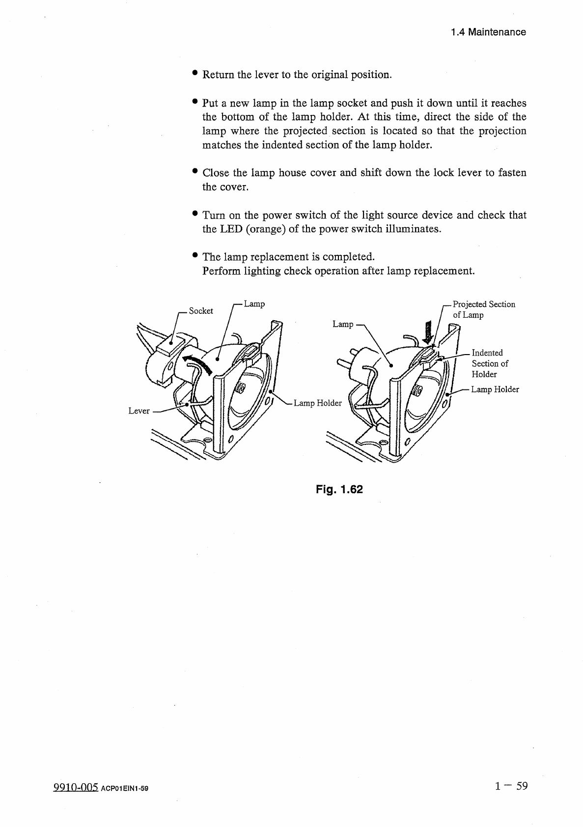
•
Return
the
lever
to
the
original
position
.
•
Put
a
new
lamp
in
the
lamp
socket
and
push
it
down
until
it
reaches
the
bottom
of
the
lamp
holder
.
At
this
time
,
direct
the
side
of
the
lamp
where
the
projected
section
is
located
so
that
the
projection
matches
the
indented
section
of
the
lamp
holder
.
•
Close
the
lamp
house
cover
and
shift
down
the
lock
lever
to
fasten
the
cover
.
•
Turn
on
the
power
switch
of
the
light
source
device
and
check
that
the
LED
(
orange
)
of
the
power
switch
illuminates
.
•
The
lamp
replacement
is
completed
.
Perform
lighting
check
operation
after
lamp
replacement
.
Lamp
Projected
Section
of
Lamp
Socket
Indented
Section
of
Holder
Lamp
Holder
Fig
.
1.62
1
—
5 9
QQio
-
nns
ACP
01
E
1
N
1
-
59
1.4
Maintenance
1.4
.
9
Replacement
of
Unrequired
Nozzle
Storage
and
Nozzle
Level
Selection
Plates
(
1
)
Time
of
Replacement
Replace
the
plate
whenever
a
dent
(
approx
.
0.2
mm
)
is
made
on
the
surface
.
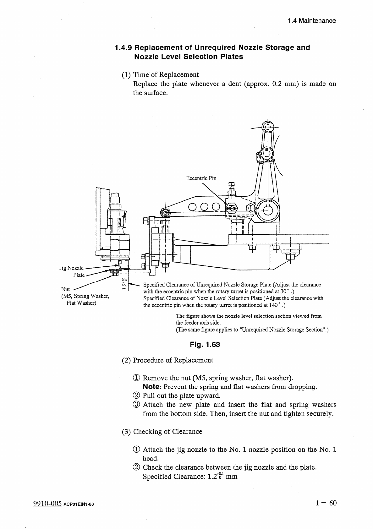
Eccentric
Pin
£
2
O O O
Jig
Nozzle
Plate
Specified
Clearance
of
Unrequired
Nozzle
Storage
Plate
(
Adjust
the
clearance
with
the
eccentric
pin
when
the
rotary
turret
is
positioned
at
30
。
•
)
Specified
Clearance
of
Nozzle
Level
Selection
Plate
(
Adjust
the
clearance
with
2
Nut
(
M
5
,
Spring
Washer
,
Flat
Washer
)
the
eccentric
pin
when
the
rotary
turret
is
positioned
at
140
°
.
)
The
figure
shows
the
nozzle
level
selection
section
viewed
from
the
feeder
axis
side
.
(
The
same
figure
applies
to
“
Unrequired
Nozzle
Storage
Section
’
’
.
)
Fig
.
1.63
(
2
)
Procedure
of
Replacement
①
Remove
the
nut
(
M
5
,
spring
washer
,
flat
washer
)
.
Note
:
Prevent
the
spring
and
flat
washers
from
dropping
.
②
Pull
out
the
plate
upward
.
③
Attach
the
from
the
bottom
side
.
Then
,
insert
the
nut
and
tighten
securely
.
plate
and
insert
the
flat
and
spring
washers
new
(
3
)
Checking
of
Clearance
①
Attach
the
jig
nozzle
to
the
No
.
1
nozzle
position
on
the
No
.
1
head
.
②
Check
the
clearance
between
the
jig
nozzle
and
the
plate
.
Specified
Clearance
:
1.2
T
mm
1
60
9910
-
005
ACP
01
EIN
1
-
60