3MAINTENANCE__O.pdf - 第81页
© tepter 1 Page 2.1 Sensitivity Adjustment of Unit P . C . B . B . B . R . Detection Photosensor 2.2 Selection of P . C . B . Flow Direction ( L / R ) 2 - 1 2 - 4 9910 - 005 ACP 01 E 1 NCC 2
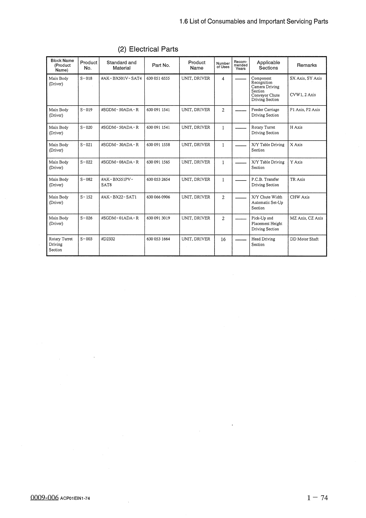
1.6
List
of
Consumables
and
Important
Servicing
Parts
(
2
)
Electrical
Parts
Block
Name
(
Product
Name
)
Recom
-
mended
Years
Applicable
Sections
Product
Standard
and
Material
Product
Name
Number
of
Uses
Part
No
.
Remarks
No
.
#
AK
-
BX
501
V
-
SAT
4
Component
Recognition
Camera
Driving
Section
Conveyor
Chute
Driving
Section
SX
Axis
,
SY
Axis
Main
Body
(
Driver
)
S
-
018
630
051
6555
UNIT
,
DRIVER
4
CVWl
,
2
Axis
Feeder
Carriage
Driving
Section
Main
Body
(
Driver
)
S
-
019
#
SGDM
-
50
ADA
-
R
630
091
1541
UNIT
,
DRIVER
FI
Axis
,
F
2
Axis
2
Main
Body
(
Driver
)
S
-
020
#
SGDM
-
50
ADA
-
R
630
091
1541
UNIT
,
DRIVER
Rotary
Turret
Driving
Section
H
Axis
S
-
021
#
SGDM
-
30
ADA
-
R
UNIT
,
DRIVER
X
/
Y
Table
Driving
Section
X
Axis
Main
Body
(
Driver
)
630
091
1558
Main
Body
(
Driver
)
S
-
022
#
SGDM
-
08
ADA
-
R
630
091
1565
UNIT
,
DRIVER
X
/
Y
Table
Driving
Section
YAxis
P
.
C
.
B
.
Transfer
Driving
Section
Main
Body
(
Driver
)
S
-
082
#
AK
-
BX
551
PV
-
SAT
8
630
053
2654
UNIT
,
DRIVER
TR
Axis
Main
Body
(
Driver
)
S
-
152
#
AK
-
BX
22
-
SAT
1
X
/
Y
Chute
Width
Automatic
Set
-
Up
Section
CHW
Axis
630
066
0906
UNIT
,
DRIVER
2
Main
Body
Priver
)
S
-
026
#
SGDM
-
01
ADA
-
R
630
091
3019
UNIT
,
DRIVER
Pick
-
Up
and
Placement
Height
Driving
Section
MZ
Axis
,
CZ
Axis
2
Rotary
Turret
Driving
Section
S
-
003
#
D
2332
630
053
1664
UNIT
,
DRIVER
Head
Driving
Section
DD
Motor
Shaft
16
nnoQ
-
nn
6
1
-
7 4
ACP
01
EIN
1
-
74
©
tepter
1
Page
2.1
Sensitivity
Adjustment
of
Unit
P
.
C
.
B
.
B
.
B
.
R
.
Detection
Photosensor
2.2
Selection
of
P
.
C
.
B
.
Flow
Direction
(
L
/
R
)
2
-
1
2
-
4
9910
-
005
ACP
01
E
1
NCC
2
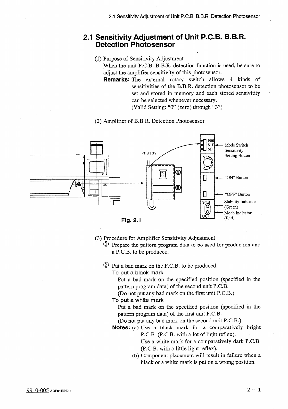
2.1
Sensitivity
Adjustment
of
Unit
P
.
C
.
B
.
B
.
B
.
R
.
Detection
Photosensor
2.1
Sensitivity
Adjustment
of
Unit
P
.
C
.
B
.
B
.
B
.
R
.
Detection
Photosensor
(
1
)
Purpose
of
Sensitivity
Adjustment
When
the
unit
P
.
C
.
B
.
B
.
B
.
R
.
detection
function
is
used
,
be
sure
to
adjust
the
amplifier
sensitivity
of
this
photosensor
.
Remarks
:
The
external
rotary
switch
allows
4
kinds
of
sensitivities
of
the
B
.
B
.
R
.
detection
photosensor
to
be
set
and
stored
in
memory
and
each
stored
sensivitity
can
be
selected
whenever
necessary
.
(
Valid
Setting
:
“
0
”
(
zero
)
through
“
3
”
)
(
2
)
Amplifier
of
B
.
B
.
R
.
Detection
Photosensor
•
n
酬
S
—
Mode
Switch
Sensitivity
Setting
Button
D
□
.
“
ON
”
Button
31
□
一
“
OFF
”
Button
Stability
Indicator
(
Green
)
^
—
Mode
Indicator
(
Red
)
TF
S
01
Fig
.
2.1
(
3
)
Procedure
for
Amplifier
Sensitivity
Adjustment
①
Prepare
the
pattern
program
data
to
be
used
for
production
and
a
P
.
C
.
B
.
to
be
produced
.
②
Put
a
bad
mark
on
the
P
.
C
.
B
.
to
be
produced
.
To
put
a
black
mark
Put
a
bad
mark
on
the
specified
position
(
specified
in
the
pattern
program
data
)
of
the
second
unit
P
.
C
.
B
.
(
Do
not
put
any
bad
mark
on
the
first
unit
P
.
C
.
B
.
)
To
put
a
white
mark
Put
a
bad
mark
on
the
specified
position
(
specified
in
the
pattern
program
data
)
of
the
first
unit
P
.
C
.
B
.
(
Do
not
put
any
bad
mark
on
the
second
unit
P
.
C
.
B
.
)
Notes
:
(
a
)
Use
a
black
mark
for
a
comparatively
bright
P
.
C
.
B
.
(
P
.
C
.
B
.
with
a
lot
of
light
reflex
)
.
Use
a
white
mark
for
a
comparatively
dark
P
.
C
.
B
.
(
P
.
C
.
B
.
with
a
little
light
reflex
)
.
(
b
)
Component
placement
will
result
in
failure
when
a
black
or
a
white
mark
is
put
on
a
wrong
position
.
2
—
1
QQ
10
-
005
ACP
01
E
1
N
2
-
1