3MAINTENANCE__O.pdf - 第84页
2.1 Sensitivity Adjustment of Unit P . C . B . B . B . R . Detection Photosensor ⑫ Use the X / Y table sensitivity is properly adjusted . Use several component - placed P . C . B . ’ s to check whether the photosensor wo…
2.1
Sensitivity
Adjustment
of
Unit
P
.
C
.
B
.
B
.
B
.
R
.
Detection
Photosensor
③
Place
the
P
.
C
.
B
.
to
be
produced
on
the
X
/
Y
table
.
Then
,
use
the
X
/
Y
table
test
(
PLACEMENT
POSITION
/
STEP
OPERATION
)
to
move
the
bad
mark
on
the
first
unit
P
.
C
.
B
.
until
it
is
located
under
the
photosensor
.
Notes
:
(
a
)
The
step
No
.
at
the
“
X
/
Y
TABLE
TEST
”
display
does
not
represent
the
location
of
the
bad
mark
.
(
b
)
When
the
X
/
Y
table
test
(
P
.
E
.
C
.
CAMERA
POSITION
/
STEP
OPERATION
)
is
used
,
the
sensitivity
cannot
be
adjusted
because
the
bad
mark
does
not
move
to
the
area
under
the
photosensor
.
④
Set
the
[
OPERATION
/
SET
UP
]
switch
to
the
“
SET
UP
”
side
and
open
the
safety
door
.
Press
the
[
CLEAR
ALARM
]
key
to
turn
off
only
the
alarm
sound
and
continue
your
work
.
⑤
Specify
the
number
(
memory
No
.
)
of
the
amplifier
’
s
rotary
switch
and
open
the
plastic
cover
of
the
amplifier
.
Note
:
Hold
the
lower
side
of
the
plastic
cover
and
pull
it
forward
to
open
,
⑥
Set
the
mode
switch
of
the
amplifier
to
the
“
SET
”
side
.
⑦
Press
the
“
ON
”
button
.
Be
sure
to
release
your
finger
from
the
button
wihtin
3
seconds
.
When
the
“
ON
”
mode
is
accepted
,
the
stability
indicator
(
green
)
blinks
and
the
mode
indicator
(
red
)
illuminates
.
⑧
Close
the
safety
door
,
set
the
[
OPERATION
/
SET
UP
]
switch
to
the
“
OPERATION
”
side
,
and
press
the
[
RESET
]
button
.
After
that
,
continue
to
perform
the
X
/
Y
table
test
until
the
bad
mark
of
the
second
unit
P
.
C
.
B
.
is
located
under
the
photosensor
.
⑨
Set
the
[
OPERATION
/
SET
UP
]
switch
to
the
“
SET
UP
,
,
side
and
open
the
safety
door
.
Then
,
press
the
[
CLEAR
ALARM
]
key
to
turn
off
the
alarm
and
continue
your
work
.
⑩
Press
the
“
OFF
”
button
.
Be
sure
to
release
your
finger
from
the
button
wihtin
3
seconds
.
When
there
is
enough
difference
in
the
intensity
of
received
light
between
“
ON
”
and
“
OFF
”
modes
and
a
bad
mark
can
be
detected
in
a
stable
condition
,
the
stability
indicator
blinks
twice
.
Otherwise
,
the
indicator
blinks
continuously
15
times
.
In
this
case
,
re
-
perform
the
adjustment
②
and
follow
the
subsequent
steps
.
⑪
After
the
sensitivity
adjustment
,
set
the
mode
switch
of
the
amplifier
to
the
“
RUN
”
side
and
close
the
plastic
cover
of
the
amplifier
.
2
-
2
991
0
-
005
ACP
01
E
1
N
2
-
2
2.1
Sensitivity
Adjustment
of
Unit
P
.
C
.
B
.
B
.
B
.
R
.
Detection
Photosensor
⑫
Use
the
X
/
Y
table
sensitivity
is
properly
adjusted
.
Use
several
component
-
placed
P
.
C
.
B
.
’
s
to
check
whether
the
photosensor
works
normally
.
Black
Mark
Position
without
a
bad
mark
:
The
mode
indicator
(
red
)
illuminates
.
Position
with
a
bad
mark
:
The
mode
indicator
(
red
)
extinguishes
.
White
Mark
Position
with
illuminates
.
Position
without
a
bad
mark
:
The
mode
indicator
(
red
)
extinguishes
.
test
and
check
whether
not
the
or
bad
mark
:
The
mode
indicator
(
red
)
a
Note
:
Although
the
X
/
Y
table
operation
is
performed
even
on
a
unit
P
.
C
.
B
.
which
has
a
bad
mark
during
this
X
/
Y
table
test
,
no
components
are
placed
in
actual
production
.
2
—
3
QQ
10
-
005
ACP
01
EIN
2
-
3
2.2
Selection
of
P
.
C
.
B
.
Flow
Direction
(
L
/
R
)
2.2
Selection
of
P
.
C
.
B
.
Flow
Direction
(
LVR
)
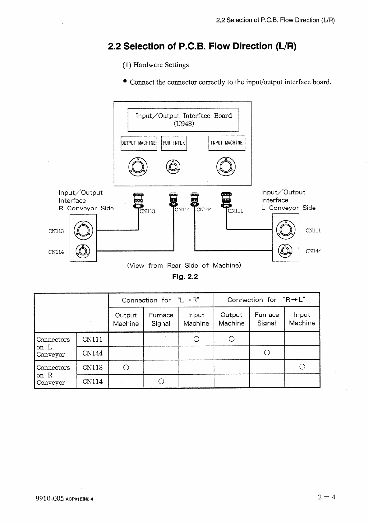
(
1
)
Hardware
Settings
•
Connect
the
connector
correctly
to
the
input
/
output
interface
board
.
Input
/
Output
Interface
Board
(
U
943
)
INPUT
MACHINE
OUTPUT
MACHINE
FUR
INTLK
input
/
Output
Interface
R
Conveyor
Side
Input
/
Output
Interface
L
Conveyor
Side
m
CN
114
CN
144
cm
ii
CN
113
CN
111
CN
113
CN
144
CN
114
(
View
from
Rear
Side
of
Machine
)
Fig
.
2.2
Connection
for
“
R
-
>
L
”
Connection
干
or
“
L
-
»
R
”
Output
Machine
Furnace
Signal
Input
Machine
Output
Machine
Furnace
Signal
Input
Machine
O
O
Connectors
on
L
Conveyor
CN
111
O
CN
144
O
o
Connectors
on
R
Conveyor
CN
113
O
CN
114
2
一
4
QQ
10
-
005
ACP
01
E
1
N
2
-
4