3MAINTENANCE__O.pdf - 第89页
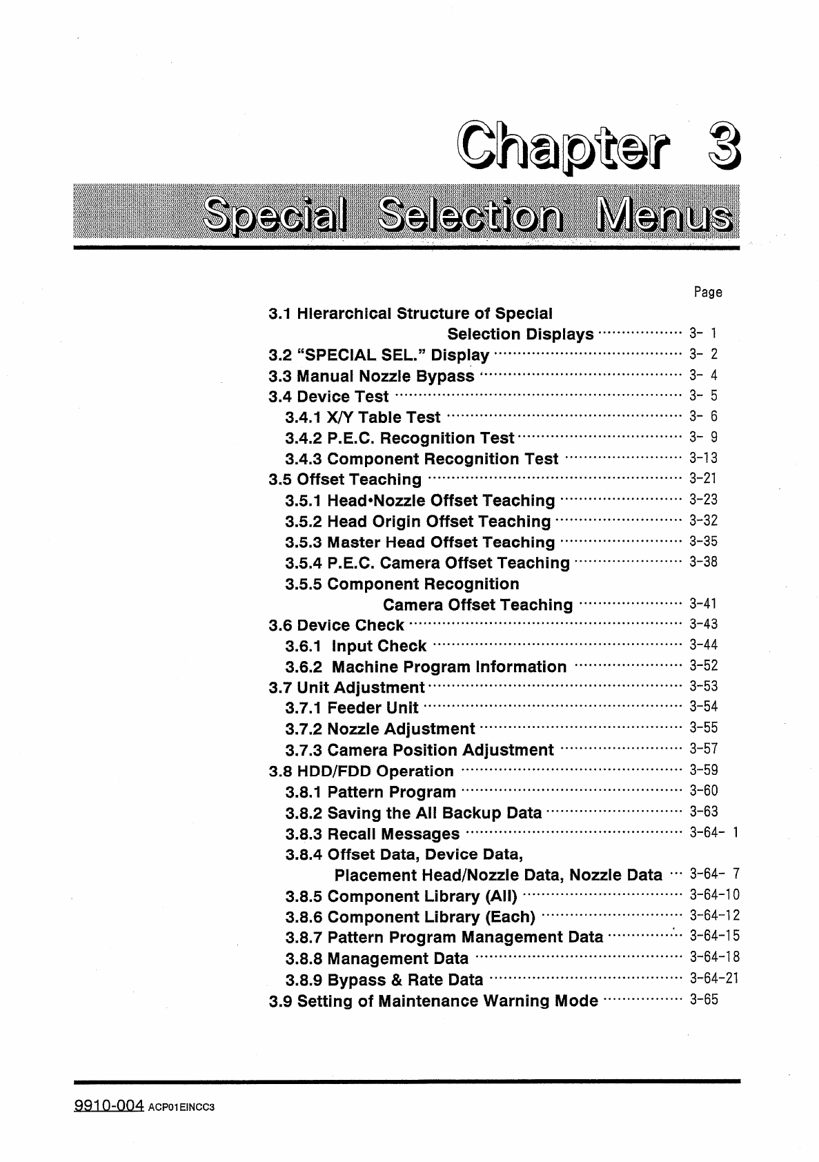
Ohupter S Page 3.1 Hierarchical Structure of Special Selection Displays 3 - 1 3 - 2 3.2 “ SPECIAL SEL . ” Display 3.3 Manual Nozzle Bypass 1 3.4 Device Test 3 - 4 3 - 5 3 - 6 3.4 . 1 X / Y Table Test 3.4 . 2 P . E . C . …
2.2
Selection
of
P
.
C
.
B
.
Flow
Direction
(
L
/
R
)
s
)
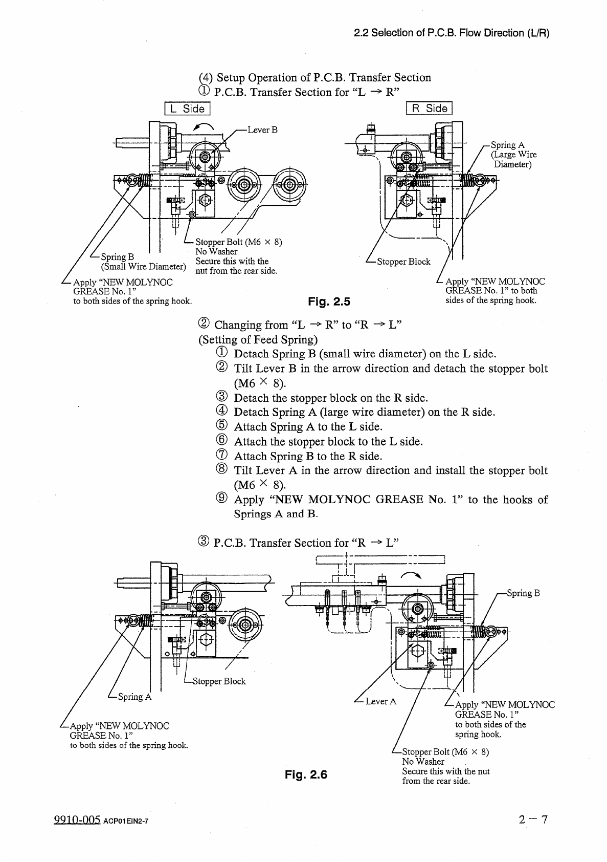
Setup
Operation
of
P
.
C
.
B
.
Transfer
Section
P
.
C
.
B
.
Transfer
Section
for
“
L
R
”
R
Side
[
L
Side
]
A
•
Lever
B
■
E
•
Spring
A
(
Large
Wire
Diameter
)
I
中
Stopper
Bolt
(
M
6
x
8
)
No
Washer
Secure
this
with
the
nut
from
the
rear
side
.
/
乙
Spring
B
/
(
Small
Wire
Diameter
)
Apply
“
NEW
MOLYNOC
GREASE
No
.
1
”
to
both
sides
of
the
spring
hook
.
Stopper
Block
Apply
“
NEW
MOLYNOC
GREASE
No
.
1
”
to
both
sides
of
the
spring
hook
.
Fig
.
2.5
②
Changing
from
“
L
(
Setting
of
Feed
Spring
)
①
Detach
Spring
B
(
small
wire
diameter
)
on
the
L
side
.
②
Tilt
Lever
B
in
the
arrow
direction
and
detach
the
stopper
bolt
(
M
6
X
8
)
.
③
Detach
the
stopper
block
on
the
R
side
.
④
Detach
Spring
A
(
large
wire
diameter
)
on
the
R
side
.
⑤
Attach
Spring
A
to
the
L
side
.
⑥
Attach
the
stopper
block
to
the
L
side
.
⑦
Attach
Spring
B
to
the
R
side
.
⑧
Tilt
Lever
A
in
the
arrow
direction
and
install
the
stopper
bolt
(
M
6
X
8
)
.
⑨
Apply
Springs
A
and
B
.
—
R
”
to
“
R
—
L
”
fNEW
MOLYNOC
GREASE
No
.
1
”
to
the
hooks
of
③
P
.
C
.
B
.
Transfer
Section
for
“
R
—
L
”
£
■
Spring
B
>
topper
Block
Spring
A
Apply
“
NEW
MOLYNOC
GREASE
No
.
ls
,
to
both
sides
of
the
spring
hook
.
•
Apply
“
NEW
MOLYNOC
GREASE
No
.
1
”
to
both
sides
of
the
spring
hook
.
•
Stopper
Bolt
(
M
6
x
8
)
No
Washer
Secure
this
with
the
nut
from
the
rear
side
.
Fig
.
2.6
2
—
7
QQ
10.005
ACP
01
EIN
2
-
7
Ohupter
S
Page
3.1
Hierarchical
Structure
of
Special
Selection
Displays
3
-
1
3
-
2
3.2
“
SPECIAL
SEL
.
”
Display
3.3
Manual
Nozzle
Bypass
1
3.4
Device
Test
3
-
4
3
-
5
3
-
6
3.4
.
1
X
/
Y
Table
Test
3.4
.
2
P
.
E
.
C
.
Recognition
Test
3.4
.
3
Component
Recognition
Test
-
3.5
Offset
Teaching
3.5
.
1
Head
*
Nozzle
Offset
Teaching
…
'
3.5
.
2
Head
Origin
Offset
Teaching
•
…
.
3.5
.
3
Master
Head
Offset
Teaching
…
1
3.5
.
4
P
.
E
.
C
.
Camera
Offset
Teaching
3.5
.
5
Component
Recognition
Camera
Offset
Teaching
3
-
9
3
-
13
3
-
21
3
-
23
3
-
32
3
-
35
3
-
38
3
-
41
3
-
43
3.6
Device
Check
3
-
44
3.6
.
1
Input
Check
3.6
.
2
Machine
Program
Information
3.7
Unit
Adjustment
3.7
.
1
Feeder
Unit
3
-
52
3
-
53
3
-
54
3
-
55
3.7
.
2
Nozzle
Adjustment
3.7
.
3
Camera
Position
Adjustment
3.8
HDD
/
FDD
Operation
3.8
.
1
Pattern
Program
3.8
.
2
Saving
the
All
Backup
Data
-
3.8
.
3
Recall
Messages
3.8
.
4
Offset
Data
,
Device
Data
,
Placement
Head
/
Nozzle
Data
,
Nozzle
Data
…
3
-
6 4
-
7
3
-
64
-
10
3
-
57
3
-
59
3
-
60
3
-
63
3.8
.
5
Component
Library
(
All
)
3.8
.
6
Component
Library
(
Each
)
3.8
.
7
Pattern
Program
Management
Data
3.8
.
8
Management
Data
3.8
.
9
Bypass
&
Rate
Data
3.9
Setting
of
Maintenance
Warning
Mode
•
3
-
64
-
12
3
-
64
-
15
3
-
64
-
18
3
-
64
-
21
3
-
65
9910
-
004
ACP
01
EINCC
3
3.1
Hierarchical
Structure
of
Special
Selection
Displays
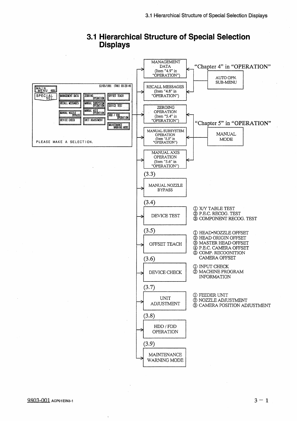
3.1
Hierarchical
Structure
of
Special
Selection
Displays
MANAGEMENT
DATA
(
Item
“
4.9
”
in
“
OPERATION
”
)
“
Chapter
4
”
in
“
OPERATION
AUTO
OPN
.
SUB
-
MENU
12
/
05
/
1991
(
THU
)
08
:
29
:
46
RECALL
MESSAGES
(
Item
“
4
,
8
”
in
OPERATION
”
)
jgoi
OFFSET
TEACH
J
MANAGEMENT
DATA
ZEB
01
HG
0
PERAT
10
BECALL
MESSAGES
UANUAL
腿
M
|
DEViCE
TEST
ZEROING
、
.
OPERATION
今
〈
Item
“
5.4
”
in
“
OPERATION
”
)
MANUAL
KTION
A
"
,
槛
DEVICE
CHECK
UNIT
ADJUSTMENT
cc
Chanter
5
,
5
in
“
OPERATION
>
5
flm
MANUAL
SUBSYSTEM
OPERATION
(
Item
"
5.5
”
in
“
OPERATION
”
)
MANUAL
MODE
PLEASE
MAKE
A
SELECTION
.
MANUAL
AXIS
OPERATION
(
Item
“
5.6
”
in
“
OPERATION
”
)
(
33
)
MANUAL
NOZZLE
BYPASS
(
3.4
)
①
X
/
Y
TABLE
TEST
②
P
.
E
.
C
.
RECOG
.
TEST
③
COMPONENT
RECOG
.
TEST
DEVICE
TEST
(
3.5
)
①
HEAD
-
NOZZLE
OFFSET
②
HEAD
ORIGIN
OFFSET
③
MASTER
HEAD
OFFSET
④
P
.
E
.
C
.
CAMERA
OFFSET
⑤
COMP
.
RECOGNITION
CAMERA
OFFSET
①
INPUT
CHECK
②
MACHINE
PROGRAM
INFORMATION
OFFSET
TEACH
(
3.6
)
DEVICE
CHECK
(
3.7
)
①
FEEDER
UNIT
②
NOZZLE
ADJUSTMENT
③
CAMERA
POSITION
ADJUSTMENT
UNIT
ADJUSTMENT
-
>
(
3.8
)
HDD
/
FDD
OPERATION
(
3.9
)
MAINTENANCE
WARNING
MODE
Q
803
-
001
3
-
1
ACP
01
EIN
3
-
1